This doesn't really make sense. After the freq doublers there will be a squaring
circuit. After that squaring circuit there should be a reasonably clean square
wave with typically some small amount of ringing or overshoot. Either the DAC
(delta sigma or R2R) is triggering correctly from the leading (or trailing) edge of
master clock or it is not.
TCD
What you will get is a square wave that has every other rising edge slightly displaced, so a slightly long period, a slightly short period, a slightly long period, a slightly short period and so on. That's exactly what single-bit sigma-delta DACs can't handle well, especially continuous-time DACs that are not FIRDACs or that are FIRDACs with no suppression at half the sample rate.
Yes you are right on Marcel. I couldn't quite visualize this so fired up LTspice and observed the zero crossing time distortion patterns when adding sub
harmonics at 1/2, 2/3 and 1/3 fundamental freq.
There is reference to this in various white papers when the oscillator OP freq is derived (multiplied) from a lower freq source. But I gues this also applies
to using crystal in overtone modes.
So where does this leave us with various types of DS DAC's? What is the best
way to mitigate any deleterious effects? Are we chasing ultra low close in phase noise down a rabbit hole at the expense of other things that may be
more important?
TCD
Last edited:

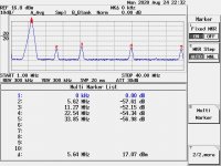
I do, and I also think the level with respect to the carrier is what matters, which is -52.75 dB if I understand the picture. When I have the time I'll run a simulation to demonstrate the effect on an ideal continuous-time single-bit sigma-delta DAC.
I wouldn't; it just produces sidebands right next to the desired signal that should be masked quite well. Of course it doesn't hurt to minimize such artefacts rather than to discuss if they are audible.
It's no so, you can try yourself, it was empirically demonstrated several times.
I have experimented myself, you should do the same.
But if you think so, I'm very curious if you explain the reason why MSB offers the Femto Clock and NDK the DuCuLon, they are very low phase noise oscilaltors that means "close to the carrier" not at 6 MHz from the carrier.
BTW, I agree with Terry, there is no effects neither with crappy sigma-delta DAC, -53dB cannot modulates nothing, the timing is not affected.
And again if you are so worried you can add more output filter to achieve -120dB and up (unuseful IMHO).
What you will get is a square wave that has every other rising edge slightly displaced, so a slightly long period, a slightly short period, a slightly long period, a slightly short period and so on. That's exactly what single-bit sigma-delta DACs can't handle well, especially continuous-time DACs that are not FIRDACs or that are FIRDACs with no suppression at half the sample rate.
I believe you are wrong, keep in mind that the Driscoll oscillator we have presented, that's pure sinewave output, has around -60dB 2nd harmonic, so not much different than the duplicated one.
But you cannot drive any DAC with a pure sinusoidal waveform, you need a sine to square converter.
Well, when you convert the sine wave into square wave the sub-harmonics of the oscillator are fully canceled, while you are charging the output with huge odd harmonics.
It's obvious since a square wave is a sine wave charged with infinite odd harmonics.
So, what kind of clock do you think to use to feed a sigma-delta DAC considering that according to your reasoning sine wave oscillators and even square wave oscillators are not suitable?
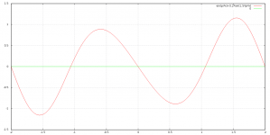
Imagine you are a slicer and you are confronted with the attached waveform (which has a grossly exaggerated component at 1.5 times the frequency to make the picture clearer). How are you going to turn that into a square wave where the rising edges are nicely equidistant?
Attachments

Well, it's no so, -60dBm means a power of 1000 times lower then the carrier and this means that the squarer neglects the harmonics.
The sine to square converter is not a linear device, it simply switches from 0 to 1 and from 1 to 0 at a certain voltage treshold, so it will switch at 22MHz not at 28MHz.
I have already said that a pure sine wave oscillator like the Driscoll has the second harmonics at 60 dB, so you are claiming that an oscillator capable to drive a sigma-delta DAC does not exists in the real world, that's obviously not true.
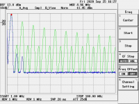
Moreover, take a look at a 5MHz CMOS output clock spectrum, as you see the harmonics are much greater than the sub-harmonics of the doubler.
Then in your opinion a CMOS output oscillator is not capable to clock correctly a sigma-delta DAC, I don't believe.
The sine to square converter is not a linear device, it simply switches from 0 to 1 and from 1 to 0 at a certain voltage treshold, so it will switch at 22MHz not at 28MHz.
I have already said that a pure sine wave oscillator like the Driscoll has the second harmonics at 60 dB, so you are claiming that an oscillator capable to drive a sigma-delta DAC does not exists in the real world, that's obviously not true.
Moreover, take a look at a 5MHz CMOS output clock spectrum, as you see the harmonics are much greater than the sub-harmonics of the doubler.
Then in your opinion a CMOS output oscillator is not capable to clock correctly a sigma-delta DAC, I don't believe.
Attachments
...We still don't have any sense of "diminishing returns" on phase noise wrt noise floor limits of DAC's.
At some point it would be inconceivable that lower noise from the reference will actually reduce the "distortions" at the dac output.
I was patiently waiting for someone to mention this.
This is a very valid point & the first requirement to consider in any system design. Thumbs up for Damian (1audio).

Cheers: Alex
Last edited:
Imagine you are a slicer and you are confronted with the attached waveform (which has a grossly exaggerated component at 1.5 times the frequency to make the picture clearer). How are you going to turn that into a square wave where the rising edges are nicely equidistant?
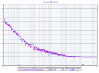
And this is a SOTA oscillators, phase noise plot and harmonics spectume analysis.
Not much difference against the duplicated one.
So a SOTA oscillator (you can take a Wenzel or a Oscilloquartz if you want) is not capable to clock a sigma-delta DAC?
Attachments
Exactly. Harmonics don't matter: when you don't care about small DC offsets, a sigma-delta DAC is not sensitive to spurs at exact multiples of the clock frequency (about the only thing it isn't sensitive to).
Getting back to the sliced sum of a sine wave at the desired frequency and a small one at 1.5 times the desired frequency: when you write out the equations, you will find that with the worst possible phase relations, the time between two rising zero crossings is 1 +/- arcsin(beta)/pi times the ideal period time, where beta is the ratio of the amplitude of the spur at 1.5 times the desired frequency to the amplitude of the desired sine wave. In the best case, the rising zero crossings don't shift at all because the sine wave at 1.5 times the desired frequency happens to cross zero at the same timepoints as the desired sine wave; in fact you can see this happening for the falling zero crossings in the first figure. You will usually end up somewhere between these extremes.
After slicing, you get a square wave with, in the worst case and counting from rising edge to rising edge, alternating clock cycles of 1 + arcsin(beta)/pi and 1 - arcsin(beta)/pi times the ideal length. For a -52.75 dBc spur, beta is 0.002304092976 and the periods are 733.4162219 ppm too long and 733.4162219 ppm too short. This is the worst case, let's assume +/- 500 ppm for the typical case.
When you have a single-bit continuous-time non-return-to-zero sigma-delta DAC (such as the noDAC from this forum, The Best DAC is no DAC ) or a two-tap return-to-zero FIRDAC (such as the valve DAC, Valve DAC from Linear Audio volume 13 ), the bit weight is proportional to the period time. Therefore, alternating 500 ppm too long and 500 ppm too short clock periods lead to 500 ppm too large and 500 ppm too small bit weights.
This bit weight that gets modulated with half the clock frequency can mix down the idle tones around fs/2 that straightforward sigma-delta modulators have. Without any signal or offset, the idle tone is exactly at fs/2 and mixing it down just causes some offset. With a small signal or offset, the idle tone shifts from fs/2 and mixing it down can cause a tone in the audio band. In fact, as the desired signal modulates the idle tone, you get a complete FM modulate added to the signal.
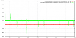
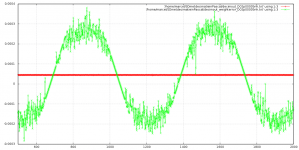
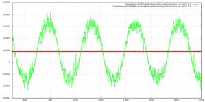
To demonstrate this, I have simulated a sixth-order slightly chaotic sigma-delta modulator and a low-pass filter with and without alternating +/- 500 ppm bit weight errors and with 0, 0.00005 and 0.0001 at the input. The Pascal program used for the simulation is attached, as are the results. The red traces are without and the green traces with weight errors. From left to right: 0 input, 0.00005 DC in and 0.0001 DC in. The x-axes are in samples after decimation by a factor of 64 and the y-axes are in arbitrary units, the largest signal that can be handled without overload is somewhere between 0.5 and 1 and the level used for the largest signal peaks would typically be 0.5. Hence, the mixed down idle tones are about 66 dB below the largest signal.
Mind you, the sigma-delta modulator and DAC type I have assumed are almost worst case for sensitivity to clock subharmonics at odd multiples of fs/2 (almost, because a sigma-delta without chaos or dithering would be even worse). A switched capacitor DAC or a FIRDAC with a notch at fs/2 would be less sensitive. For my own valve DAC, I use a sigma-delta algorithm with an embedded pulse width modulator with randomly rotated patterns, I expect that subharmonics will only cause some noise floor increase with that.
The multibit DACs that Andrea prefers shouldn't have any issue with a bit of second subharmonic. It's just a matter of choosing the right clock generation for the application.
After slicing, you get a square wave with, in the worst case and counting from rising edge to rising edge, alternating clock cycles of 1 + arcsin(beta)/pi and 1 - arcsin(beta)/pi times the ideal length. For a -52.75 dBc spur, beta is 0.002304092976 and the periods are 733.4162219 ppm too long and 733.4162219 ppm too short. This is the worst case, let's assume +/- 500 ppm for the typical case.
When you have a single-bit continuous-time non-return-to-zero sigma-delta DAC (such as the noDAC from this forum, The Best DAC is no DAC ) or a two-tap return-to-zero FIRDAC (such as the valve DAC, Valve DAC from Linear Audio volume 13 ), the bit weight is proportional to the period time. Therefore, alternating 500 ppm too long and 500 ppm too short clock periods lead to 500 ppm too large and 500 ppm too small bit weights.
This bit weight that gets modulated with half the clock frequency can mix down the idle tones around fs/2 that straightforward sigma-delta modulators have. Without any signal or offset, the idle tone is exactly at fs/2 and mixing it down just causes some offset. With a small signal or offset, the idle tone shifts from fs/2 and mixing it down can cause a tone in the audio band. In fact, as the desired signal modulates the idle tone, you get a complete FM modulate added to the signal.
To demonstrate this, I have simulated a sixth-order slightly chaotic sigma-delta modulator and a low-pass filter with and without alternating +/- 500 ppm bit weight errors and with 0, 0.00005 and 0.0001 at the input. The Pascal program used for the simulation is attached, as are the results. The red traces are without and the green traces with weight errors. From left to right: 0 input, 0.00005 DC in and 0.0001 DC in. The x-axes are in samples after decimation by a factor of 64 and the y-axes are in arbitrary units, the largest signal that can be handled without overload is somewhere between 0.5 and 1 and the level used for the largest signal peaks would typically be 0.5. Hence, the mixed down idle tones are about 66 dB below the largest signal.
Mind you, the sigma-delta modulator and DAC type I have assumed are almost worst case for sensitivity to clock subharmonics at odd multiples of fs/2 (almost, because a sigma-delta without chaos or dithering would be even worse). A switched capacitor DAC or a FIRDAC with a notch at fs/2 would be less sensitive. For my own valve DAC, I use a sigma-delta algorithm with an embedded pulse width modulator with randomly rotated patterns, I expect that subharmonics will only cause some noise floor increase with that.
The multibit DACs that Andrea prefers shouldn't have any issue with a bit of second subharmonic. It's just a matter of choosing the right clock generation for the application.
Attachments
Last edited:
How could I prepare a clock, to be fed into one of my (better?) dacs..
I have a nice quality 11,289 clock.. Maybe doing a cruel doubler, could compare the resulting signal to an NDK SDA clock (which would give a similar, sligthly better phase noise signature, apart from subharmonics..)
I have a nice quality 11,289 clock.. Maybe doing a cruel doubler, could compare the resulting signal to an NDK SDA clock (which would give a similar, sligthly better phase noise signature, apart from subharmonics..)
Yes you are right on Marcel. I couldn't quite visualize this so fired up LTspice and observed the zero crossing time distortion patterns when adding sub
harmonics at 1/2, 2/3 and 1/3 fundamental freq.
There is reference to this in various white papers when the oscillator OP freq is derived (multiplied) from a lower freq source. But I gues this also applies to using crystal in overtone modes.
I don't expect problems with crystals running in overtone modes. You then simply have a resonator with various resonant frequencies and use some additional circuitry to select the resonance that you want. I can't see why that would cause any subharmonics. Maybe you get a slight noise bump at the frequency of the fundamental resonance, but no tone.
So where does this leave us with various types of DS DAC's? What is the best way to mitigate any deleterious effects? Are we chasing ultra low close in phase noise down a rabbit hole at the expense of other things that may be more important?
TCD
That depends entirely on the type of sigma-delta DAC, unfortunately also on details that are often kept out of DAC chip datasheets.
Getting back to the sliced sum of a sine wave at the desired frequency and a small one at 1.5 times the desired frequency: when you write out the equations, you will find that with the worst possible phase relations, the time between two rising zero crossings is 1 +/- arcsin(beta)/pi times the ideal period time, where beta is the ratio of the amplitude of the spur at 1.5 times the desired frequency to the amplitude of the desired sine wave. In the best case, the rising zero crossings don't shift at all because the sine wave at 1.5 times the desired frequency happens to cross zero at the same timepoints as the desired sine wave; in fact you can see this happening for the falling zero crossings in the first figure. You will usually end up somewhere between these extremes.
After slicing, you get a square wave with, in the worst case and counting from rising edge to rising edge, alternating clock cycles of 1 + arcsin(beta)/pi and 1 - arcsin(beta)/pi times the ideal length. For a -52.75 dBc spur, beta is 0.002304092976 and the periods are 733.4162219 ppm too long and 733.4162219 ppm too short. This is the worst case, let's assume +/- 500 ppm for the typical case.
When you have a single-bit continuous-time non-return-to-zero sigma-delta DAC (such as the noDAC from this forum, The Best DAC is no DAC ) or a two-tap return-to-zero FIRDAC (such as the valve DAC, Valve DAC from Linear Audio volume 13 ), the bit weight is proportional to the period time. Therefore, alternating 500 ppm too long and 500 ppm too short clock periods lead to 500 ppm too large and 500 ppm too small bit weights.
This bit weight that gets modulated with half the clock frequency can mix down the idle tones around fs/2 that straightforward sigma-delta modulators have. Without any signal or offset, the idle tone is exactly at fs/2 and mixing it down just causes some offset. With a small signal or offset, the idle tone shifts from fs/2 and mixing it down can cause a tone in the audio band. In fact, as the desired signal modulates the idle tone, you get a complete FM modulate added to the signal.
To demonstrate this, I have simulated a sixth-order slightly chaotic sigma-delta modulator and a low-pass filter with and without alternating +/- 500 ppm bit weight errors and with 0, 0.00005 and 0.0001 at the input. The Pascal program used for the simulation is attached, as are the results. The red traces are without and the green traces with weight errors. From left to right: 0 input, 0.00005 DC in and 0.0001 DC in. The x-axes are in samples after decimation by a factor of 64 and the y-axes are in arbitrary units, the largest signal that can be handled without overload is somewhere between 0.5 and 1 and the level used for the largest signal peaks would typically be 0.5. Hence, the mixed down idle tones are about 66 dB below the largest signal.
Mind you, the sigma-delta modulator and DAC type I have assumed are almost worst case for sensitivity to clock subharmonics at odd multiples of fs/2 (almost, because a sigma-delta without chaos or dithering would be even worse). A switched capacitor DAC or a FIRDAC with a notch at fs/2 would be less sensitive. For my own valve DAC, I use a sigma-delta algorithm with an embedded pulse width modulator with randomly rotated patterns, I expect that subharmonics will only cause some noise floor increase with that.
The multibit DACs that Andrea prefers shouldn't have any issue with a bit of second subharmonic. It's just a matter of choosing the right clock generation for the application.
Wow! Pascal reminds me when i used to develop in Delphi... fine times... it was simpler (regardless of the known memory management problem of the earlier versions, I did stop with Delphi 7), now with Visual Studio is more complicated, although it's a strong tool it has become a wide world that covers IMHO too much aspects in a single application.
Back to the topic, as I said I would use sigma-delta DAC for cooking, so I cannot argue.
I'm not sure that sub-harmonics cross the sine to square converter, so I will do a comparison as soon as I find the time (spectrum analysis before and after the squarer).
Anyway you can simply add more filters at the output of the doubler to reduce the amplitude of the sub-harmonics.
But maybe the right question is: does it worth to use high clock frequency to convert from digital to analog?
I don't believe, the best oscillators are in the 5Mhz region so I would use this frequency to convert.
I was patiently waiting for someone to mention this.
This is a very valid point & the first requirement to consider in any system design. Thumbs up for Damian (1audio).
Cheers: Alex
Hi Alex and Demian,
I believe it's a little difficult to demonstrate the relation between the phase noise and the sonic result measuring the distortion at the output of the DAC.
But I have experimented several times that this relation exists, the lower the close in noise of the oscillator the better the sonic result.
And not me only, several members in this thread reported huge sound improvemenent moving to a better quality clock.
Better quality means lower close-in phase noise, the noise flooor is always similar in whatever oscillator, the Crystek performs -160dBc.
If it's not true this thread does not make sense, and it does not make sense MSB to offer the FemtoClock at 19000 USD, and neither NDK to build its DuCuLon.
But maybe the right question to answer could be the following: is there a limit beyond that the sound improvement stops?
I believe we can answer the question soon.
Many members reported huge improvements when moving from the Crystek, NDK or Accusilicon oscillators to the old Driscoll (TWTMC-D emitter coupled).
It's a good oscillator but not a SOTA one.
Then I ask the members who will move to the new Driscoll or Differential oscillators to report their impressions after the replacement.
Andrea
But maybe the right question is: does it worth to use high clock frequency to convert from digital to analog?
I don't believe, the best oscillators are in the 5Mhz region so I would use this frequency to convert.
I can't think of any advantage of high clock frequencies for a multibit converter that needs little or no noise shaping. I mean a classical 14...18 bit DAC.
It can be useful for a sigma-delta DAC. I use 27 MHz for my DIY sigma-delta DAC because I wanted it to work reasonably well over the feline auditory range and I wanted to make it a quasi-multibit system by embedding a pulse width modulator in the loop while still having enough oversampling. The higher the clock rate, the more oversampling and (unfortunately) the more settling issues.
Last edited:
I respect your preference, but I cannot see any reason to generate noise and then to try shaping it in order to mitigate its impact.
And moreover you have to use higher clock frequencies that means higher phase noise (or jitter if you prefer).
Maybe be I'm a trivial ordinary man, but I believe I can make it simpler avoiding to generate noise.
This is the reason why we are developing a pair of multibit DACs.
And moreover you have to use higher clock frequencies that means higher phase noise (or jitter if you prefer).
Maybe be I'm a trivial ordinary man, but I believe I can make it simpler avoiding to generate noise.
This is the reason why we are developing a pair of multibit DACs.
Unfortunately with multibit DACs you are then dealing with ENOB, DNL and INL stuff and the best multibit DAC's are limited in resolution (in the technical sense) compared to the best delta sigma DACs. At which point you then ask what is the jitter/phase noise floor/limit of the DAC; as in lower jitter won't produce higher accuracy.
And its fair to say that, like distortion, a single number for jitter can be really misleading. DACs may respond differently to different types of jitter. And RMS vs. Peak to Peak plus look at the crest factor of the random jitter. Are there big jumps and how often do they appear.
MSB making a kajillion dollar clock reflects more of the opportunity to get the money than clearly demonstrable improvement in performance. I do not believe that space shuttle tiles will somehow make the clock work better. or there would be papers published on their application. Nasa is a major consumer of SOTA clocking solutions so they would have an interest.
Really good execution of the basics (low EMI/RFI, low noise and freedom from modulation back from the audio stream etc.) will account for a lot of improvement in a DAC.
RE doubler- Gerhard's suggestion of using a cheap crystal as a filter to remove the subharmonic makes sense in this context. However I have never seen suggestions that PLL's will add noise. Usually it seems the other way when properly executed. And straight harmonic correction should not have any spurs.
Unfortunately with multibit DACs you are then dealing with ENOB, DNL and INL stuff and the best multibit DAC's are limited in resolution (in the technical sense) compared to the best delta sigma DACs.
... I have lately been thinking in relation to multibit DACs - wouldn't it be possible to somehow conceive a "correction setup" which corrects for the finite precision of both the DAC switches and the resistors used so that the distortion could be significantly reduced?
I reckon that it could be done e.g. using an FPGA with a correction file so that when a certain bit sequence is transferred to the DAC then the FPGA corrects for the non-linearities of the DAC related to this bit sequence. I don't know, however, how well it would work under changing dynamic conditions as music is ...
Cheers,
Jesper
The Lavry Dac did that. It had something like a 1 hour warm up and then did a selftest to derive corrections for each step. Probably the best audio r2r execution ever. Rare and expensive on the used market. 96K.max sample rate.
I believe you cannot understand the impact of the clock quality measuring the distortion of the DAC and neither you can mathematically demonstrate the relation between them.
My impressions (not only mine) are based on listening and I can assure that the difference are impressive.
Regardless of the prices MSB and NDK have built SOTA oscillators to be used in digital to analog conversion.
Is that a marketing operation only?
If so we are losing time, this thread does not make sense, you can get Crystek, Accusilicon, Tentlabs and cheap NDK for 25 Euro or less, or the Silabs Si570 for 10 Euro if you think the best way is using a PLL.
Maybe is a question of approach, we believe that the timing section of the DAC is the most crucial while other look at the distortion. Then we look for the best close-in noise from the oscillator and there is no room for PLL, the phase noise plot of the Si570 is in the datasheet and it's orrible.
In our opinion the oscillator has to run free without any correction and when you have achieved -150dBc at 10 Hz from the carrier there is no reason to implement a continuos adjustement that inevitably add noise.
Our vision is the most simple: start from the best feedback free solution rather than applying a post-hoc correction.
Then we prefer to run a SOTA oscillator rather than apply a PLL, we prefer a multibit DAC rather than a noise generator to be shaped, and we prefer to start from a linear device to implement a zero feedback single ended rather than apply a lot of feedback to correct the non-linearity of the device.
We also like to avoid complex electrical crossover in favor of mechanical-acoustical filters.
We respect those who runs delta-sigma DAC, but after a lot of comparison we prefer the old multibit DACs.
So we are developing some devices following our approach and our vision.
We have designed the frequency doubler for the audio community and not for us, we don't need high clock frequencies, we will run our DACs at 5/6 MHz.
Then, sorry but we have no time to work more around the doubler, it already performs very well, and if you need to decrease the sub-harmonics content you can simply add more filters or just a crystal at the output.
In the past we have also thought to implement a static correction of the DAC bits (again no room for dynamic correction), but finally we have decided that it does not worth because we believe that the timing is more important than the bit precision and so we have focused on the clock.
- Status
- Not open for further replies.
- Home
- Source & Line
- Digital Line Level
- The Well Tempered Master Clock - Building a low phase noise/jitter crystal oscillator