Also, Croven Crystals - Motional Resistance Rs = 80ohms max. Laptech crystal - Motional Resistance Rs = 60ohms max.
All of my Laptech crystals measured a resistance below 45ohms and a few below 40ohms.
Croven Crystal - Q factor = 500
Laptech crystal - Q factor = 500
All of my Laptech crystals measured a Q factor over 500 and two of them have touched 600.
Q-factor of 500 must be wrong, even 500K @5MHz would be no reason to get excited.
I can get a Q of 450 from old Siemens K1 pot cores.
The Morion crystal taken from my dead MV89A OCXO has a Q of 2.2 or 2.3 million,
depending on how I measure it on the network analyzer @ 5MHz and I see that
Laptech claims a Q of 1 or 2 Million depending on the case. This HC37 that looks like a
fat TO-5 seems to be at an advantage.
And Rs goes with the square of the overtone. For a given Q, a high Rs is an advantage
because such a crystal is less impressed by other resistances such as Re or varicaps
for AFC. But a high overtone comes with a thick blank which drives cost higher.
There a new cuts from Morion and Temex in England to fill the void that BVAs have left.
I'm all ears if someone has details.
Sorry to see that this thread has gone the way of a Kindergarten kit soldering course
with a fan club without a clue, instead of real discussion about technology.
cheers, Gerhard
Last edited:
"Sorry to see that this thread has gone the way of a Kindergarten kit soldering course with a fan club without a clue, instead of real discussion about technology."
Those of us that cannot contribute to the design do fill a role in reaching MOQ. We'll try to keep quiet and send money when requested by the elite.
Those of us that cannot contribute to the design do fill a role in reaching MOQ. We'll try to keep quiet and send money when requested by the elite.
For sync master clock operation, the signal from freq doublers should pass through a fanout buffer and then feed dac and transport?
Also how long could be the coax rg402 cable between freq doublers and dac?
Thank you verry much!
Also how long could be the coax rg402 cable between freq doublers and dac?
Thank you verry much!
Edit :
For sync master clock operation, the signal from sqaurer should pass through a fanout buffer and then feed dac and transport?
Also how long could be the coax rg402 cable between freq doublers and squarer?
Thank you verry much!
For sync master clock operation, the signal from freq doublers should pass through a fanout buffer and then feed dac and transport?
Also how long could be the coax rg402 cable between freq doublers and dac?
Thank you verry much!
It depends on the architecture of your digital system, if you use a FIFO buffer you don't need to sync the transport, otherwise if your system is synchronous then you need a clock distribution circuit, so a fanout buffer could be used.
A coax cable 1 meter long or so can be used without problem (it's around the lenght of the cable we are using to connect the oscillator to the Timepod when measuring the phase noise).
Q-factor of 500 must be wrong, even 500K @5MHz would be no reason to get excited.
I can get a Q of 450 from old Siemens K1 pot cores.
The Morion crystal taken from my dead MV89A OCXO has a Q of 2.2 or 2.3 million,
depending on how I measure it on the network analyzer @ 5MHz and I see that
Laptech claims a Q of 1 or 2 Million depending on the case. This HC37 that looks like a
fat TO-5 seems to be at an advantage.
And Rs goes with the square of the overtone. For a given Q, a high Rs is an advantage
because such a crystal is less impressed by other resistances such as Re or varicaps
for AFC. But a high overtone comes with a thick blank which drives cost higher.
There a new cuts from Morion and Temex in England to fill the void that BVAs have left.
I'm all ears if someone has details.
Sorry to see that this thread has gone the way of a Kindergarten kit soldering course
with a fan club without a clue, instead of real discussion about technology.
cheers, Gerhard
All the 5.6448 MHz SC-Cut 3rd overtone crystals I have received from Laptech have a Q in the range 2-2.4M and ESR around 100 ohm.
With the Driscoll oscillator the higher the ESR the greater the loaded Q, since the crystal is placed in the emitter circuit.
If we assume the Re of the bjt around 4 ohm a crystal with 100 ohm ESR means a loaded Q around 96% (100/100+4), while if the ESR of the crystal is 40 ohm the loaded Q is 90% (40/40+4).
The 11.2896 MHz SC-Cut crystals has a Q around 1M and the ESR is around 80 ohm, so the Q is half the one of the 5.6448 MHz and the loaded Q is a little lower (95%).
Then the loaded Q of the 5 MHz crystal is around 2M while for the 11 MHz the loaded Q is around 950k.
To achieve similar performance the unloaded Q of the 11MHz crystal should be doubled, that means higher overtone and much higher cost.
"Sorry to see that this thread has gone the way of a Kindergarten kit soldering course with a fan club without a clue, instead of real discussion about technology."
Those of us that cannot contribute to the design do fill a role in reaching MOQ. We'll try to keep quiet and send money when requested by the elite.
I believe that this thread could share both technical discussion and implementation infos, since at the end the goal is to use these oscillators in a real audio digital system.
@Gerhard
We have got the crystals and we have designed the oscillators to use them in our ideal audio system.
For our personal use we were interested in the 5/6 MHz oscillators only, but since other members need higher clock frequencies we have expanded the project to 22/24 MHz and up to 98 MHz using the frequency doublers.
On the other side it was interesting working with duplicators to confirm the theory in the real world.
Last edited:
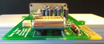
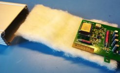
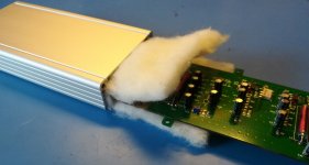
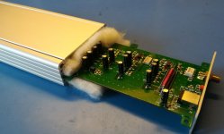
Vibrations and thermal coupling.
Vibrations and thermal coupling.
I attach a few pictures to show a good way to place the crystal on the board.
You can use a pair of neoprene cylinders to decouple the crystal from the board, then you can wrap the oscillator section with a polyester fiber or wool foil.
Vibrations and thermal coupling.
I attach a few pictures to show a good way to place the crystal on the board.
You can use a pair of neoprene cylinders to decouple the crystal from the board, then you can wrap the oscillator section with a polyester fiber or wool foil.
Attachments
Hi again, Andrea & all - back again a little early from a vacation that was somewhat influenced by the Covid-19 situation ... But still fine, though ...
I have been reading up on this thread and am still impressed with what you are doing and how promising it appears to be. Thanks again for doing this effort ;-)
However, one thing comes to mind in relation to your decision not to publish the schematics for the oscillators and that is that from a system integration point of view I would prefer to integrate at least the squarer and likely the doubler into the PCB of the DAC & ADC I will be using these oscillators for.
A main reason for this is that when first a signal is digital it is quite noisy & wideband and therefore I would like to be in control of where these signals emit noise - and this is much easier when integrated on the converter PCB.
Thus - any chance you & your collaborator(s) would consider making those circuitries known?
Cheers,
Jesper
Hi Jesper,
I'm sorry but it's not my decision, as I said my co-developer does not agree to publish the schematics so I have to respect his will.
About the squarer, this is the entry version to be used with Ian's device and it's so simple that you can do the reverse engineering from the PCB and the BOM.
But if you are looking for a ultimate solution you have to wait several months until the top version of the sine to square converter will be ready.
On the other hand the frequency doubler does not handle square wave signals, here we are still in sine wave domain, so I would take it far from the other circuits to avoid any beating with the other frequencies involved.
Hi Andrea,
& thanks again for your feedback ... will just consider what to do then.
Have a good day ;-)
Jesper
& thanks again for your feedback ... will just consider what to do then.
Have a good day ;-)
Jesper
Hi Andrea.
If a Buffalo BS-GS2016 switch only works with LVCMOS output clocks, is there problems to use any of Yours clocks?
If a Buffalo BS-GS2016 switch only works with LVCMOS output clocks, is there problems to use any of Yours clocks?
No problem, you can use all the new oscillators since they need to be followed by a sine to square converter that's LVCMOS output.
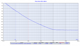
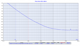
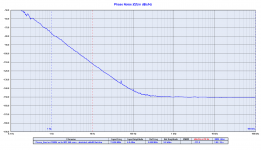
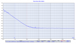
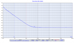
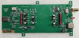
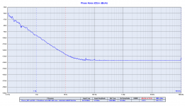
New Pierce oscillator TWTMC-PXO from 5/6 MHz up to 45/49 MHz
I attach a picture and the phase noise plots of the new Pierce oscillator from 5 MHz up to 24 MHz (we cannot measure 45/49 MHz due to the upper limit of the Timepod).
I attach a picture and the phase noise plots of the new Pierce oscillator from 5 MHz up to 24 MHz (we cannot measure 45/49 MHz due to the upper limit of the Timepod).
Attachments
-
 TWTMC-PXO Pierce 24576 - shielded att6dB Batt.png126.8 KB · Views: 232
 -
 TWTMC-PXO Pierce 225792 - shielded att6dB Batt.png126.6 KB · Views: 220
 -
 TWTMC-PXO Pierce 12288 - shielded att6dB Batt.png126.2 KB · Views: 515
 -
 TWTMC-PXO Pierce 112896 - shielded att6dB Batt.png126.1 KB · Views: 519
 -
 TWTMC-PXO Pierce 6144 - shielded att6dB Batt.png126.5 KB · Views: 545
 -
 TWTMC-PXO Pierce 56448 - shielded att6dB Batt.png125 KB · Views: 560
 -
 TWTMC-PXO_01.jpg226.5 KB · Views: 628
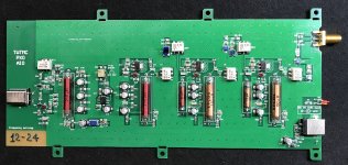
New Pierce All in One oscillator TWTMC-PXO-AIO from 11/12 MHz and 22/24 MHz
I attach a picture and the phase noise plots of the new Pierce All in One oscillator. The base frequencies are 5.6448 MHz and 6.144 MHz, then there are a couple of frequency doublers to provide 11.2896/22.5792 MHz or 12.288/24.576 MHz (output configurable).
The phase noise performance are very good for a AT-Cut crystal.
This combo oscillator could be also used to multiply 6 and 6.25 MHz for those who need 24/25 MHz.
Attachments
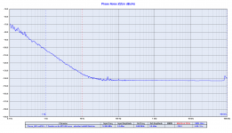
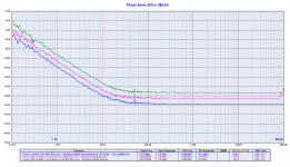
I forgot a plot related to the TWTMC-PXO-AIO, this is the comparison between the base oscillator at 6.144 Mhz and the multiplied output at 12.288 MHz and 24.576 MHz.
The theory is confirmed again, around 6dB was added for each duplication.
The theory is confirmed again, around 6dB was added for each duplication.
Attachments
Q-factor of 500 must be wrong, even 500K @5MHz would be no reason to get excited.
I can get a Q of 450 from old Siemens K1 pot cores.
The Morion crystal taken from my dead MV89A OCXO has a Q of 2.2 or 2.3 million,
depending on how I measure it on the network analyzer @ 5MHz and I see that
Laptech claims a Q of 1 or 2 Million depending on the case. This HC37 that looks like a
fat TO-5 seems to be at an advantage.
And Rs goes with the square of the overtone. For a given Q, a high Rs is an advantage
because such a crystal is less impressed by other resistances such as Re or varicaps
for AFC. But a high overtone comes with a thick blank which drives cost higher.
There a new cuts from Morion and Temex in England to fill the void that BVAs have left.
I'm all ears if someone has details.
Sorry to see that this thread has gone the way of a Kindergarten kit soldering course
with a fan club without a clue, instead of real discussion about technology.
cheers, Gerhard
Hi Gerhard
Yes,I missed "K" because I was a little in a hurry when i wrote this so i didn't check it out.
Others who read realized the unintentional mistake so they had no need to comment,except you.
You’re right that even 500K at 5MHz wouldn’t be a cause for excitement.The only thing
don't understand ,where did you dig up that frequency and where did I mention 5MHz ???
Comment #2793
Quote: "A few months ago I contacted Croven Crystals and sent an inquiry for crystal quartz 16.9344 MHz / HC43U / SC cut -3rd OT"!
500K is a pretty good value for frequency 16.9344MHz and all my Laptech crystals were 500K +. Two of them were 600K+. Btw., Laptech has a little conservative ratings.
Yes,high Rs can be an advantage and does not have to. It depends on the design.
I'm not a designer and my oscillator was designed by my very good friend, who is also a designer.
Between the two offers, I estimated that the offer of Laptech is better value for the money.
By the way, Croven is a bigger player in the crystal market than Laptech.But at Croven they were fair and their sales agent told me that Croven was probably not a place for hobbyists because
of their price structure. The data on paper did not reflect a significant difference in quality, but more in price.
One detail caught my attention.Quote:" We would also recommend an etch finish not polished finish which is non-standard and will drive cost very high".
As far as I know, polishing has to do with the persistence of the Q factor over a long period of time and there is obviously a crystal from Croven (as they said), had a significantly higher price with a polishing finish.
I’m surprised you didn’t comment on that fact within technology.I would love to hear your opinion here.Cheers!
- Status
- Not open for further replies.
- Home
- Source & Line
- Digital Line Level
- The Well Tempered Master Clock - Building a low phase noise/jitter crystal oscillator