Hi Gerhard
Yes,I missed "K" because I was a little in a hurry when i wrote this so i didn't check it out.
Others who read realized the unintentional mistake so they had no need to comment,except you.
You’re right that even 500K at 5MHz wouldn’t be a cause for excitement.The only thing
don't understand ,where did you dig up that frequency and where did I mention 5MHz ???
Well, there were 2 mistakes in one place. First the missing frequency, which makes
the cases "OMG" and "piece of crap" equally possible, and then the factor of 1000
that blows everything out of the water.
And most here would not comment on technical issues, for them it's enough
if it can be soldered without SMD and promises outstanding specs.
----
I also do not second the hype on SC-Cuts. They have the potential for slightly higher Q
and can withstand more power which makes it easier to keep the relative noise
floor down.
Some years ago I still claimed otherwise on the time nuts list, based on observations
on MTI-260 subtypes & similar, and I was promptly corrected by J.Ackerman.
I still remember the words "profoundly wrong". And he is a member of the HP gang
at Santa Clara that brought up that stress compensated cut. Some say that
SC really stands for Santa Clara.
A customer of mine had some batches of AT cut crystals near 100 MHz from
< Quarze - Quarztechnik Daun > and I got an oscillator out of
one of them at 100 MHz / 100Hz / -135dBc. You cannot do much better.
Most of the crystals were at Q=100K @ 100 MHz, some even slightly higher.
Quarztechnik has quite good prices and they also will do weird frequencies.
I have ordered there more than once. I don't know if they make SC.
cheers, Gerhard
I also did some experiments with crystal notch filters, with a crystal pair
sucking out phase noise at, say +-5 KHz of the carrier. That can be done
at very high power levels without harming the crystals. Penny crystals
are good enough for that.
Yes, the SMIQ-4 signal generator is an easy victim, it is more
a modulation- than a phase noise wonder.
sucking out phase noise at, say +-5 KHz of the carrier. That can be done
at very high power levels without harming the crystals. Penny crystals
are good enough for that.
Yes, the SMIQ-4 signal generator is an easy victim, it is more
a modulation- than a phase noise wonder.
Attachments

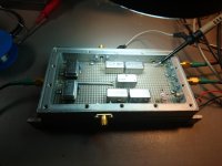
I attach a picture and the phase noise plots of the new Pierce All in One oscillator. The base frequencies are 5.6448 MHz and 6.144 MHz, then there are a couple of frequency doublers to provide 11.2896/22.5792 MHz or 12.288/24.576 MHz (output configurable).
The phase noise performance are very good for a AT-Cut crystal.
This combo oscillator could be also used to multiply 6 and 6.25 MHz for those who need 24/25 MHz.
Looking very good.
New Pierce already populated two AT crystals boards
Hi,
Frequencies doublers are already embeded in the new Pierce all in one ? Stwitchable X2 & X4 ?
But if this New Pierce board design need to be checked cause trim-pot adjustment, it could be cool to putt the two AT Xtals (frequencies choice) each user wants !
For the one as me having already AT-Cuts and wanting not necessarily close frequencies for each : For instance : a 5.x At-Cut for the NOS of the first frequencies family which are the main CDs and a 24 or a 12 for the second families for the few 24/192 material existing ?
At worst, could it be delivred for whatever reasons with the AT-Cuts but non soldered yet for the futur owner to pick-up in his own AT-Cuts collection already owned ?
That's very cool measurments both for the SC & AT crystals boards... looking forward to have it and hearing it on my pcm dacs 🙂
Theoretically every time you multiply the frequency you should get a phase noise around 6 dB worse than the basic oscillator and the phase noise plot of the doubler confirms the theory.
This allows to get better performance using the basic oscillator at lower frequency and then multiply it one or more times to achieve the required frequency.
I am confused about this.
(A) In the first sentence you are saying that frequency doubling results in 6 dB worse phase noise.
(B) In the second sentence you are saying that the frequency doubling gives better perfomance.
(A) and (B) seem to contradict each other. What's going on here?
Hi,
Frequencies doublers are already embeded in the new Pierce all in one ? Stwitchable X2 & X4 ?
Two doublers are integrated on the board.
Andrea will correct me if I am wrong, but it looks in the picture like the output config is selected 2x or 4x by choosing location for soldering a pair of SMT resistors.
Hi,
Frequencies doublers are already embeded in the new Pierce all in one ? Stwitchable X2 & X4 ?
But if this New Pierce board design need to be checked cause trim-pot adjustment, it could be cool to putt the two AT Xtals (frequencies choice) each user wants !
For the one as me having already AT-Cuts and wanting not necessarily close frequencies for each : For instance : a 5.x At-Cut for the NOS of the first frequencies family which are the main CDs and a 24 or a 12 for the second families for the few 24/192 material existing ?
At worst, could it be delivred for whatever reasons with the AT-Cuts but non soldered yet for the futur owner to pick-up in his own AT-Cuts collection already owned ?
That's very cool measurments both for the SC & AT crystals boards... looking forward to have it and hearing it on my pcm dacs 🙂
Yes, the new Pierce TWTMC-PXO-AIO has two doublers on board, so you can configure the output for 2x or 4x.
As Thom said to configure the output to 2x or 4x you have to solder a few smd 0R resistors (2 for 22/24 MHz or 1 for 11/12 MHz).
You cannot change the frequencies of the base oscillator, they are fixed 5.6448 or 6.144 MHz, so the outputs are 11/12 (x2) and 22/24 (x4). Of course it's possible to use similar crystal frequencies like 6 or 6.25 Mhz.
To clarify the relation between the duplication and the phase noise performance: theoretically every time the frequency is duplicated the phase noise will be 6db worse.
The plots I have published confirm the theory, although the close in phase noise (around 1 Hz from the carrier) is a little better than the theory.
> I am confused about this.
5 MHz is a sweet spot for low phasenoise oscillators.
An oscillator at 10 MHz would have +6 dB phasenoise, every else being equal.
But everything else is not equal it seems.
Doubling 5 MHz costs the same 6 dB, but you get better results after all.
The 6 dB cannot be avoided, but doubling avoids other errors.
The reason for the 6 dB is simply that with the same phase modulation,
the carrier period is only half as long, so the modulation is relatively stronger.
I'm just working on my cross-correlating frequency extender for the Timepod.
Seems to work as fas as I can say with the scope.
If supplied with 5V, it has two independent 80 MHz oscillators and 2 mixers
that convert either 50...80 or 80...110 MHz to 0...30 MHz for the Timepod.
Without 5V supply, it mixes everything below 400 MHz to the Timepod range,
but you must have 2 external frequency synthesizers.
It uses MCL SRA-1 mixers, a PSC2-1 power splitter, SDS reed relays to switch
between internal/external oscillators , and 2 80 MHz crystal oscillators.
Surprisingly they can drive the ring mixers directly, but then these need only 7 dBm.
I had to use parts that are in the junk box.
Attachments
Last edited:
I've only read a small part of this thread, so maybe this has been brought up before, but depending on the application and the level, the subharmonics you get from an oscillator at half the frequency with a frequency doubler could be more harmful than a slightly worse phase noise. In particular, any type of DAC that uses a single-bit sigma-delta modulate (such as native DSD DACs) will be quite sensitive to the second subharmonic because of mixing effects with an idle tone at half the sample rate.

From what I have read a really good solution is to use a low close in noise oscillator (5 MHz) to phase lock a good hf oscillator (20 MHz+). The PLL lowers the close in noise to close to that of the 5 MHz while the 20 MHz noise further from the carrier becomes the remaining noise outside of the PLL correction band. it would get lower noise further out that the multiplied noise of the LF oscillator. It means two oscillators but may get better overall results. Here is a reference: A Guide to Phase-Locked Oscillators | Atlantic Microwave One of several on the web. For 2X and maybe 4X it may not be a big issue but for 90+ MHz it may be important.
We still don't have any sense of "diminishing returns" on phase noise wrt noise floor limits of DAC's. At some point it would be inconceivable that lower noise from the reference will actually reduce the "distortions" at the dac output.
We still don't have any sense of "diminishing returns" on phase noise wrt noise floor limits of DAC's. At some point it would be inconceivable that lower noise from the reference will actually reduce the "distortions" at the dac output.


From what I have read a really good solution is to use a low close in noise oscillator (5 MHz) to phase lock a good hf oscillator (20 MHz+). The PLL lowers the close in noise to close to that of the 5 MHz while the 20 MHz noise further from the carrier becomes the remaining noise outside of the PLL correction band. it would get lower noise further out that the multiplied noise of the LF oscillator. It means two oscillators but may get better overall results. Here is a reference: A Guide to Phase-Locked Oscillators | Atlantic Microwave One of several on the web. For 2X and maybe 4X it may not be a big issue but for 90+ MHz it may be important.
We still don't have any sense of "diminishing returns" on phase noise wrt noise floor limits of DAC's. At some point it would be inconceivable that lower noise from the reference will actually reduce the "distortions" at the dac output.
With the doubler the close in phase noise is already very close to the reference oscillator (3-4 dB worse).
IMHO the PLL is not a clean solution, I think it adds more close in noise than the doubler.
And a noise floor around -164dBc is not so bad when the reference is -170dBc.
Last edited:
@MarcelvdG
And where are the subharmonics?
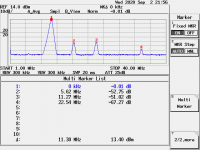
Right there in your second picture, unless I misinterpret your second picture. About -80 dBc at half the output frequency and -52.75 dBc at 3/2 times the output frequency (which would mix with the first alias of the sigma-delta idle tone).
Last edited:
At 3/2 times the output frequency is -52.75 -13.4 so the result is -66.15 dB.
And at 6MHz from the carrier do you think -66 dB is high?
BTW you can add more output filter to mitigate the harmonics, we have used a pair of them here, but you could use 5 or 6 of them, althoug I think it will be a waste.
I have to adimit I don't know much about sigma-delta DAC (I would use them to cook a hamburger in place of the microwave oven), so I cannot argue much about such a noise generator.
We have bought a Sabre DAC board from Audiophonics to test our FIFO buffer, it sounds terrible, very far from an old TDA1541A or a AD1865.
But I would be much more worry about the close in noise, that's affects heavily the sonic result, at least many member have reported so with any type of DAC.
Last edited:
Right there in your second picture, unless I misinterpret your second picture. About -80 dBc at half the output frequency and -52.75 dBc at 3/2 times the output frequency (which would mix with the first alias of the sigma-delta idle tone).
This doesn't really make sense. After the freq doublers there will be a squaring
circuit. After that squaring circuit there should be a reasonably clean square
wave with typically some small amount of ringing or overshoot. Either the DAC
(delta sigma or R2R) is triggering correctly from the leading (or trailing) edge of
master clock or it is not.
TCD
At 3/2 times the output frequency is -52.75 -13.4 so the result is -66.15 dB.
You are using relative markers, the first is 0KHz 0db, so it is what Marcel says, the sub-harmonic component is -52.75dBc.
With respect to 0dBm, that is - 39. 35dBm, but I don't see why would that count..
Andre, glad to hear you still find the venerable old TDA1541a a well served by your WTMC. I certainly do!
This doesn't really make sense. After the freq doublers there will be a squaring
circuit. After that squaring circuit there should be a reasonably clean square
wave with typically some small amount of ringing or overshoot. Either the DAC
(delta sigma or R2R) is triggering correctly from the leading (or trailing) edge of
master clock or it is not.
TCD
What you will get is a square wave that has every other rising edge slightly displaced, so a slightly long period, a slightly short period, a slightly long period, a slightly short period and so on. That's exactly what single-bit sigma-delta DACs can't handle well, especially continuous-time DACs that are not FIRDACs or that are FIRDACs with no suppression at half the sample rate.
At 3/2 times the output frequency is -52.75 -13.4 so the result is -66.15 dB.
And at 6MHz from the carrier do you think -66 dB is high?
I do, and I also think the level with respect to the carrier is what matters, which is -52.75 dB if I understand the picture. When I have the time I'll run a simulation to demonstrate the effect on an ideal continuous-time single-bit sigma-delta DAC.
But I would be much more worry about the close in noise, that's affects heavily the sonic result, at least many member have reported so with any type of DAC.
I wouldn't; it just produces sidebands right next to the desired signal that should be masked quite well. Of course it doesn't hurt to minimize such artefacts rather than to discuss if they are audible.
- Status
- Not open for further replies.
- Home
- Source & Line
- Digital Line Level
- The Well Tempered Master Clock - Building a low phase noise/jitter crystal oscillator