I would like to see some real specs on the MSB oscillators. The claims are pretty extravagant and you show how to get better numbers. Most comm standards use a higher range for measuring jitter (e.g. Sonet 12 KHz to 20 MHz) and will give lower rms jitter numbers. This is a good intro to the many ways to look at jitter: An Introduction to Jitter in Communicatio - Maxim Integrated and this for a premium oscillator mfr: http://www.mtronpti.com/sites/default/files/files/oscillator-jitter-basics.pdf
My point being that you need to know what to measure for before measuring jitter. Early on this thread was about evaluating the importance of low frequency components of jitter. Its not simple since the published evidence of jitter sensitivity shows that HF parts are more important.
I would still argue that what is important is the jitter artifacts in the audio output. Those are easier to measure since all you need is a good soundcard and FFT plus some digital test tones.
Hi Demian,
although MSB Tech does not publish the phase noise plot, they provide a grid with the measured phase noise for each distance from the carrier:
FemtoSecond Galaxy Clock Specifications:
Phase Noise at 0.1 Hz -67 db
Phase Noise at 1 Hz -99 db
Phase Noise at 10 Hz -134 db
Phase Noise at 1 kHz -157 db
Phase Noise at 10 kHz* -157 db
Phase Noise at 100 kHz -157 db
Guaranteed TIE (jitter down to 1 Hz)** .077 psec.
As you can see the jitter was measured with an integration bandwidth starting from 1Hz, not with a bandwidth suitable for telecommunication like someone is doing in another famous thread.
As I said several times the jitter measurement tells nothing if the integration bandwidth is unknown.
One can even reaches the paradox that the Eur 25 Crystek performs better than the 19000 USD MSB Femto clock, because in the broadband range the Crystek is similar or better than the MSB one.
But if you take a look at the phase noise specs then all is clear, the MSB is far better than the Crystek: at 10Hz from the carrier the MSB is 37 db better than the Crystek!
And if you measure the jitter of the Crystek down to 1 Hz the result will be several ps, not a few fs.
Human brain is very sensitive to timing error so the close in phase noise spectrum is essential to understand the quality of clock.
Andrea
I thought I would do some analysis based on published measurements of the MSB and some known state of the art oscillators.
The MSP delivers 85 fS based on the published numbers in a 1Hz to 100KHz band
The BVA, which is known to be the best close in (and a very difficult technology with a 9 month lead time) gets 180 fS under the same conditions
The Wenzel ULN which is much lower phase noise at higher frequencies gets the lowest jitter even though its the highest at 1 Hz.
What causes me to question the MSB numbers is that first its 22 MHz which would have a significantly higher phase noise to start with and then the curve doesn't show the normal close in rise. It has a single breakpoint at 100 Hz (very low) and rises faster.
Also they get much more for it than a Wenzel Bluetop would cost. $22k vs $5800 for a Wenzel bluetop (real quote from a few years ago).
And after all of this I think some effort calculating the required jitter to get 24 ENOB at 192 KHz will show the required jitter performance. Once you are there more improvement won't show.
The Crystek is much worse (no surprise). Its attached for completeness. The lowest measured frequency was 10 Hz and I extrapolated to 1 Hz so it can be compared.
Attachments


I thought I would do some analysis based on published measurements of the MSB and some known state of the art oscillators.
The MSP delivers 85 fS based on the published numbers in a 1Hz to 100KHz band
The BVA, which is known to be the best close in (and a very difficult technology with a 9 month lead time) gets 180 fS under the same conditions
The Wenzel ULN which is much lower phase noise at higher frequencies gets the lowest jitter even though its the highest at 1 Hz.
What causes me to question the MSB numbers is that first its 22 MHz which would have a significantly higher phase noise to start with and then the curve doesn't show the normal close in rise. It has a single breakpoint at 100 Hz (very low) and rises faster.
Also they get much more for it than a Wenzel Bluetop would cost. $22k vs $5800 for a Wenzel bluetop (real quote from a few years ago).
And after all of this I think some effort calculating the required jitter to get 24 ENOB at 192 KHz will show the required jitter performance. Once you are there more improvement won't show.
The Crystek is much worse (no surprise). Its attached for completeness. The lowest measured frequency was 10 Hz and I extrapolated to 1 Hz so it can be compared.
It could be very useful if they published the phase noise plot, at that price level I would get the individual measurement.
I don't know, we are talking about a commercial device, and I'm so far away from commercial dynamics.
I attach the phase noise to RMS jitter conversion of the measured Driscoll oscillator at 5.6448 MHz, it's in the region of BVA and Wenzel, maybe a little better.
I'm not surprised because an oscillator to be used in digital audio can be optimized for close in phase noise, while BVA and Wenzel have also to look at long term stability, so some compromises is needed.
It's very singular that the fundamentalist followers of the other thread continue asking to measure the jitter using an oscilloscope with an integration bandwidth suitable for telecommunication only.
I cannot understand, but as I said I gave up.
Attachments
What about Neutron Star from Newclassd? Do any of you guys have experience with that clock?
It's not a state of the art oscillator, it's yet another toy sold at a crazy price.
I thought I would do some analysis based on published measurements of the MSB and some known state of the art oscillators.
....
The Crystek is much worse (no surprise). Its attached for completeness. The lowest measured frequency was 10 Hz and I extrapolated to 1 Hz so it can be compared.
Demian,
here the measurements using QA401 Out to RME ADI-2 Pro fs input.
The point with the various oscillators, a noise figure is a must provide from the manifactor/source. But the measurement equipment cost goes into xx..xxxk$ price range.
Also, the final implementation counts, while ESS may allows a asynchronous DAC clock source mode, where others only synchronous.
The implementation and jitter figure varies do:
. Master Clock brand
. attached switch logic for the various SR 32/44.1/48 kHz based SR's and multiple of
. Used Chip as ADC & DAC
. ground issues
. connection issues as bounds signal reflections
...
IMHO is simpler & much cheaper (for DIY too) to use a fs/4 sine and measure with 2 independent ADC & DAC gear the noise bell and artifacts as my given pictures shows up.
May the current chips do not allow/permits to a certain level do the substrate noise.
Best would be an ADC with a multiple of n^2 SR to get with related as n^2 FFT. This means a sample rate with 256k would with FFT 256K provide a 1/rtHz figure and do not needs a re-scale, while artifact levels do not get false scaled.
my 2 cents
Hp
Attachments
Great post!!
Please, I would like to know the answer to the "24 ENOB at 192" question!
//
Please, I would like to know the answer to the "24 ENOB at 192" question!
//
I thought I would do some analysis based on published measurements of the MSB and some known state of the art oscillators.
The MSP delivers 85 fS based on the published numbers in a 1Hz to 100KHz band
The BVA, which is known to be the best close in (and a very difficult technology with a 9 month lead time) gets 180 fS .........snip.
24 effective number of bits- Let do some arithmetic.
First 24 bits translates into 16,777,216 discrete steps in a true 24 bit DAC or ADC, These are basically nonexistant above a very low frequency for a host of reasons but its a target to look at for jitter.
For a DAC to be accurate it needs to ouput the right voltage at the right time. That would mean that the discrete times need to be accurate to 2 to the 24th power. So we divide the sample rate into 16,777,216 parts and the output timing needs to be within 1/16777216 par of that sample rate. That translates into 3.104e-13 or around 300 fS. (I may well have an incorrect assumption or translation here but it seems correct).
In other words a 24 bit DAC cannot meet that spec if the sample interval varies by 300 fS. Many other things will alter this. For example if all that comes out is DC the sample interval matters little. And of course the 24 bit DAC is mythical. Maybe 22 bits under the best of circumstances.
And this is a little simplistic an analysis of what matters. The nature of the jitter (deterministic vs. random, peak vs average etc.) will be really important.
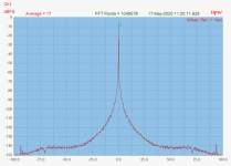
The plot HpW shows above is remarkably free of deterministic jitter. Its all random and its the composite of all the jitter mechanisms from oscillator to DAC to DAC power (which influences the thresholds). Its actually pretty good I think.
First 24 bits translates into 16,777,216 discrete steps in a true 24 bit DAC or ADC, These are basically nonexistant above a very low frequency for a host of reasons but its a target to look at for jitter.
For a DAC to be accurate it needs to ouput the right voltage at the right time. That would mean that the discrete times need to be accurate to 2 to the 24th power. So we divide the sample rate into 16,777,216 parts and the output timing needs to be within 1/16777216 par of that sample rate. That translates into 3.104e-13 or around 300 fS. (I may well have an incorrect assumption or translation here but it seems correct).
In other words a 24 bit DAC cannot meet that spec if the sample interval varies by 300 fS. Many other things will alter this. For example if all that comes out is DC the sample interval matters little. And of course the 24 bit DAC is mythical. Maybe 22 bits under the best of circumstances.
And this is a little simplistic an analysis of what matters. The nature of the jitter (deterministic vs. random, peak vs average etc.) will be really important.
The plot HpW shows above is remarkably free of deterministic jitter. Its all random and its the composite of all the jitter mechanisms from oscillator to DAC to DAC power (which influences the thresholds). Its actually pretty good I think.
The plot HpW shows above is remarkably free of deterministic jitter. Its all random and its the composite of all the jitter mechanisms from oscillator to DAC to DAC power (which influences the thresholds). Its actually pretty good I think.
Yes, we do not see on QA401 any artifacts/spurious.
Compare with #2381, so you may see & understand that the QA401 is some better than the L22, but still wort than RME ADI-2 Pro fs. The bell is as Phase/Jitter noise plot, the result of master clock mixing..
Keep in mind that Source (DAC) uses one separated HW with it's own free running master clock and the Input (ADC) uses one separated HW with it's own free running master clock.
Important is to use 2 different gear for play and sample. Otherwise coherent master clock measurement is done. Also zoom in into +/- 200Hz around the fs/4 to see the beef.
Hp
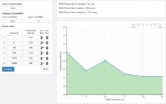
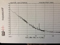
Since someone in another thread claims that the jitter measurement with a digital oscilloscope is the right and absolute way to understand the timing quality of digital audio devices (and obviously his fundamentalist followers confirm this without understand what they are talking about), I publish a pair of pictures to explain the reason why such that way is wrong.
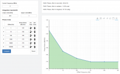
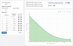
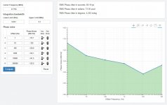
I have used a phase noise to jitter converter to emulate the jitter measurement of the Crystek CCHD-957 at 22.5792 MHz.
The calculated jitter is exactly the same that one can measure with a real gear.
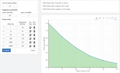
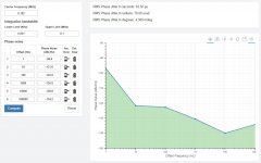
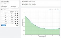
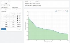
As you can see, in the first picture the jitter is calculated with an integration bandwidth 300Hz-3KHz (the standard used in telecommunication), while the second pictures shows the jitter calculated with a wider integration bandwidth, more suitable in digital audio, 1Hz to 3KHz.
The first picture tells us that the oscillator has a jitter of 37.84 fs, that's a great result! Almost like the MSB Tech Femto 33 (33 fs).
So, why you can get the Crystek for 25 Euro while you have to pay 19000 USD to get the MSB?
It's very strange such that difference if they are so similar!
The second picture explain clearly the reason: with a suitable integration bandwidth the jitter of the Crystek grows to 12.28 ps, that's almost one order of magnitude (fs to ps) worst than the MSB one.
I've not succeeded explaining this to the fundamentalist followers, maybe somebody could try one more time.
@andrea_mori
https://www.diyaudio.com/forums/dig...itter-crystal-oscillator-238.html#post6306713
I really can not get your point. Sorry about that.
1. Jitter is a time domain concept so usually we call it time jitter. Time jitter is the real signal uncertainty attribute of a clock signal. It exists in the real world and can be measured directly by a high speed digital scope in the time domain. Phase jitter is a different story. Please just don't confuse the two concepts. Phase jitter doesn't exist in the real world, it can only be calculated from phase noise plot indirectly. Phase jitter is the integration of the area under the curve of a specific phase noise plot within a specified integration bandwidth. Theoretically phase jitter will be equivalent to time jitter if it integrates through full bandwidth from frequency 0 to ∞.
2. Your first example doesn't mean anything to the real world time jitter. So I don't know why you took it for example. It's just a phase jitter that was partially integrated from 300Hz to 3KHz bandwidth. If you want to know the whole picture of real jitter performance you need to integrate throughout the full bandwidth. If you really want to use that number, you have to specify it as 37.84fs phase jitter @ 300Hz-3KHz. Again, the integration bandwidth has no business with time domain jitter measurement. It only has something to do with phase jitter calculation from phase noise plot. For a given clock signal, time jitter is existing there, integration bandwidth can only change the phase jitter calculation result but it will never change the time jitter numbers.
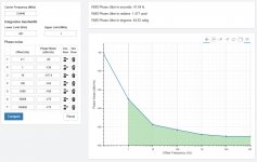
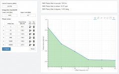
3. The 1Hz to 3KHz integration bandwidth seems to be a good range to make the phase jitter result closed to the real time jitter. However even I assume your -67dBc/Hz at 1Hz is correct (not an official number), your 12.28 ps phase jitter result was still wrong. The correct phase jitter number should be 3.12ps RMS for CCHD-957 22.5792MHz XO @1Hz to 1MHz . Please see my calculating result attached. I really worry about posting the wrong jitter calculation results could mislead other community members. Please correct me if I'm wrong.
Regards,
Ian
Attachments
Last edited:
I have said several times that jitter is a standalone number that does not say anything because it does not explain the spectrum of the noise. It's a valid measurement results for telecommunication but not for digital audio.
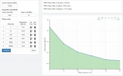
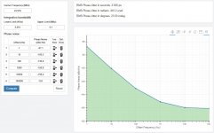
BTW I attach some phase noise plots from real measurements and RMS jitter conversions to better understand the importance of the noise spectrum.
The title of each picture refers to the measured device.
Sorry but I have no time to comment the measurements, maybe later.
P.S.
Anyway your calculated 3.12ps or my calculated 2.656ps from real measurements for the Crystek CCHD-957 means that the members got a crappy oscillators, real low noise oscilaltors are in the fS region.
I wonder how one could think to get a good oscillator for 25 Euro.
Attachments
-
 FifoPi LRCK out Phase Jitter.jpg121.3 KB · Views: 224
 -
 FifoPi SCK out Phase Jitter.jpg109.9 KB · Views: 218
 -
 FifoPi MCLK Out with Crystek CCHD-957 at 24.576 MHz Phase Jitter.jpg114.6 KB · Views: 236
 -
 RPI LRCK out Phase Jitter.jpg118.7 KB · Views: 256
 -
 RPI BCK out Phase Jitter.jpg118.9 KB · Views: 772
 -
 RPI-FifoPi LRCK Out with Crystek CCHD-957 at 24.576 MHz Phase Noise.png157.7 KB · Views: 784
 -
 RPI-FifoPi SCK Out with Crystek CCHD-957 at 24.576 MHz Phase Noise.png161.5 KB · Views: 783
 -
 FifoPi MCLK Out with Crystek CCHD-957 at 24.576 MHz Phase Noise.png126.8 KB · Views: 767
Last edited:
Andrea- do any of your oscillators have a voltage trim input? (Varactor diode) A very interesting experiment would be to feed a modulation into the clock and see if its present at the output in a phase noise plot and in the measured output of a DAC. it would also be possible to find audible thresholds for different frequencies/spectra of jitter. All the existing lit is quite old so some new measurements with lower residuals would be a great help.
Hi Demian,
unfortunately no varactor in the new oscillators.
The starting schematic of the differential oscillator uses varactors to fine tune the frequency (such 3-4 Hz) and the one of the Driscoll uses varactors in the AGC circuits, but we have removed them from the final circuits because we don't need them for our scope (and also they add noise).
Maybe I still have the first prototype board of the differential oscillator with the footprints for the varactors, even we have never mounted them (early replaced with fixed capacitors). I will do a search.
Anyway, if you tahe a look at the above plot that shows the LRCK from the Raspberry and the LRCK at the output of the FIFO, you can clearly see that what is injected at the input is reflected to the output at timing DAC level (30 to 100 Hz from the carrier) although the master clock (the Crystek toy) does not show such noise.
But this is another story that involve the architecture of the interposed devices.
For sure the phase noise analysis tells much more than the standalone jitter measurement since the spectrum of the noise helps a lot to understand and solve the timing problem.
Andrea
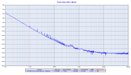
And now the same measurements with the Driscoll oscillator at 22.5792 MHz.
Attachments
-
 FifoPi LRCK out Phase Jitter Driscoll.jpg114.4 KB · Views: 197
 -
 FifoPi SCK out Phase Jitter Driscoll.jpg117.9 KB · Views: 212
 -
 FifoPi MCLK Out with Driscoll at 22.5792 MHz Phase Jitter.jpg117 KB · Views: 235
 -
 RPI-FifoPi LRCK Out with Driscoll at 22.5792 MHz Phase Noise.png166.6 KB · Views: 246
 -
 RPI-FifoPi SCK Out with Driscoll at 22.5792 MHz Phase Noise.png171.6 KB · Views: 331
 -
 FifoPi MCLK Out with Crystek 24.576 _ Driscoll 22.5792 MHz Phase Noise.png160.6 KB · Views: 272
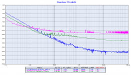
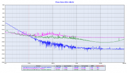
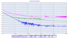
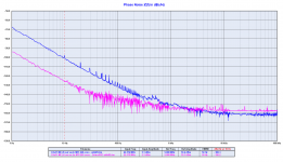
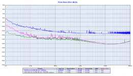
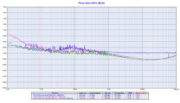
And now a few comparison of the phase noise plots:
- Fifo MCLK Out Crystek vs Driscoll
- Fifo SCK Out RPI vs Crystek vs Driscoll
- Fifo LRCK Out RPI vs Crystek vs Driscoll
The plots tell themselves, so better if avoid any comment.
Maybe the designer could comment the measurements.
I only have to say that the Crystek is 26dB worse than the Driscoll at 10Hz from the carrier, as expected.
Attachments
Last edited:
Looks very good.. similar L(f) to 22.579MHz Pulsar Clock from 1Hz to 10Hz, and proabably a lot less expensive!.
Can you measure below 1Hz?..
Can you measure below 1Hz?..
Attachments
Last edited:
Thans Andrea, Those plots have been very helpful getting a better insight what is going on.
Two things popped out for me. I might be wrong in this so happy to learn.
1
As the PCM1794 does the conversion at BCK / SCK this is what I looked for in your plots. I see that the Driscoll is like 10 dB better at 10 Hz and after that it is almost similar.
2. The MCK from the FiFoPi is a direct measurement from the clock, whereas the SCK went through the On board logic. Jitter is introduced in this process.
I am still not sure, what impacts the perceived gain of sound quality more, the 10Hz or the 100 Hz spec... I believe I recall that by experiments done, it was round the 100 Hz mark. But I might be wrong.
Not sure I can do anything with this information, other than trying to correlate what I hear on sound reproduction with and without fifopi and the kind of clocks used and as said, how that correlates...
- Status
- Not open for further replies.
- Home
- Source & Line
- Digital Line Level
- The Well Tempered Master Clock - Building a low phase noise/jitter crystal oscillator