@ Bisesik
😉 I like your smiley icon...
but in all seriousness, I do like the discussions between Ian and Andrea, as I learn a lot extra about all the aspects of phase noise and jitter. So I certainly welcome this.
I hope the tone stays ok (even though I did not like so much the "fundamentalist" comments from Andrea, but ok, I am a big boy, so can handle that)
On the topic itself. I mentioned already, the only thing which counts for me (and many other DAC chips) is the BCK/SCK signal - so the LR jitter is of little importance - even though I like the discussion why the differences are as they are between the two measurements.
And it seems, that there is, next to the audible (!) improvement using the fifopi with relatively good clocks like Accusilicon (even though they are called toys), room for improvement with clocks which are better thanks to taking care of crucial design elements.
Supersurfer also mentioned the improvement using Andrea's previuos clocks with fifopi and the DDDAC 1794 dac setup
so my Question to Andrea would be if he could advise what someone would need to buy from your group buy to be used in the FiFoPi as a complete best possible set assuming one would like to play up to 192kHz tracks ?
that would be nice
If you would like to play up to 192kHz with the FifoPi and the PCM1794 I believe you need 22/24 MHz master clock oscillators (the designer should confirm).
Although the noise floor of the FifoPi SCK output is not optimal (20-25 dB worse than the master clock) there is anyway some improvements of the close in phase noise against the Raspberry BCK output.
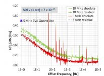
If you look at the second phase noise plot in post #2400 you see:
- at 1 Hz from the carrier, the phase noise of the FifoPi SCK with the Driscoll oscillator is more than 30 dB better than the Raspberry (-114dBc vs -82dBc)
- at 10 Hz from the carrier it's still 23 dB better (-125dBc vs -102dBc)
The same measurement with the Crystek oscillator is worse, so you can assume the better the oscillator the lower the close in phase noise (and jitter) of the FifoPi SCK output.
So there will be two options:
- the Driscoll or the Differential oscillator at 22/24 MHz (TWTMC-DRIXO or TWTMC-EXO)
- the Driscoll or the Differential oscillator at 5/6 MHz or 11/12 MHz followed by one or two doublers (TWTMC-DRIXO or TWTMC-EXO + one or two TWTMC-DBM)
To do the final choice you have to wait until we finish the tests and we publish the results of all the combination.
Next question.. It's my fault but where do I find the DDS generator spectra?
I have not published the phase noise plot of the DDS generator, at the time I have done the measurement (a couple of months ago) it was out of interest, but I'll do a search of the saved data.
I have published here the measurements because I felt there was no interest in the Fifo thread, indeed some members did ask me to stop annoying.
But this thread is about Crystal Oscillators rather than FIFO and reclocker, so the discussion is off topic here, and I think should be moved to the FIFO thread. The oscillators in this thread were not designed specifically for FifoPi, far from it, they were designed to be used in our digital chain we are working on.
So if there is renewed interest in FIFO measurements I publish all the plots in the FIFO thread.
All the phase noise measurements have been copied in the FIFO thread to continue the discussion in the most appropriate thread.
Asynchronous I2S FIFO project, an ultimate weapon to fight the jitter
Asynchronous I2S FIFO project, an ultimate weapon to fight the jitter
@ andrea_mori
"a good divider does not add any jitter/phase noise"
Can you take an example?
Thanks,
Ian
"a good divider does not add any jitter/phase noise"
Can you take an example?
Thanks,
Ian
Not yet, we are working on this, it will be implemented in our SOTA audio system (not in the Lite version).
In any case, such dividers already exist, we are optimizing our version for digital audio.
Please, be patient, our times is very long, we are not in a hurry, the project is for ourselves (although we will share the design with the diy audio community).
Just an example.
P.S.
I forgot, you cannot reach this performance with FPGA and flip-flop, you have to change the approach.
Attachments
Last edited:
@ andrea_mori
I didn't see any example from the attachment. Do you mean that "no additive jitter" clock divider doesn't exist by now, or you want to use a PLL based clock divider (Loop with feedback)?
Thanks,
Ian
I didn't see any example from the attachment. Do you mean that "no additive jitter" clock divider doesn't exist by now, or you want to use a PLL based clock divider (Loop with feedback)?
Thanks,
Ian
Last edited:
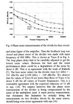
The above attachment shows the phase noise of the carrier to be divided (trace A) and the phase noise of the divider by four (trace B).
As you can see the divided signal is 8dB better than the original signal, although the improvement should be the theoretically 12dB.
So such dividers already exist and no PLL is needed.
This is another one using the same tecnique, it achieves -150dBc at 1 Hz and -162dBc at 10Hz from the carrier.
But as I said above forget FPGA & flip-flop to achieve these results.
Attachments
Last edited:
@ andrea_mori
If your example was from this old artical:
https://zenodo.org/record/1268157/files/article.pdf
I don't think the real product is exist for now.
And even for the solution, I don't think it can be implemented into a digital audio system. Just unrealistic.
BTW, the result is also not good. Too much spurs...
Thanks,
Ian
You are wrong, the real product is ready to be tested and optimized.
It looks like you have not understood, in audio we don't need a microwave signal at 8 GHz, we simply need a pair of SOTA oscillators at 5/6 MHz to divide down to 44/192 kHz with a very low noise divider like the regenerative one.
You are free to continue enjoying with FPGA and flip-flop, but you have just seen the results.
The spurs of the measurements of your FifoPi have been suppressed, because they are out of interest, but if you want I have saved the original data and so I can publish the plots with spurs.
"BTW, the result is also not good", I hope you are joking, -150dBc at 1 Hz from the carrier and -177dBc noise floor!
I have to remind the phase noise of the FifoPi SCK: -74 dBc with the Crystek and -96 dBc with the Driscoll at 1 Hz from the carrier and -120/130 dBc noise floor, that means the phase noise of the FifoPo is 75 dB worse and the noise floor is 50-60 dB worse.
Ian, I see your FifoPi for 159 Eur sold by Audiophonics, as I already said I think it's a decent device at affordable and honest price.
But please, forget to achieve "ultimate" performance at this price level, it's not possible, you have to redesign all with a totally different architecture.
I wonder if you really think you are getting the performance of a SOTA system like MSB Tech (for example) for a few hundred Eur, since you usually name "ultimate" your designs.
I also wonder why you continue to reply here while I have posted all the plots on your dedicated thread, that would be the most appropriate to discuss about the FifoPi measurements.
Last edited:
@ andrea_mori
I'm discussing the measurement topic that you started. It seems you are trying to degrade other's solutions by something that doesn't exist by now or not true. So I have to post my point.
"I hope you are joking, -150dBc at 1 Hz"
The spurs were not the -150dBc. Could already be very close to 100dBc around 100Hz offset. I think you know what those spurs mean in the phase noise plot.
I respect your contribution to the oscillators to the community. But as an engineer, I have to tell the truth, if I see something that is not correct, I need to point it out.
After carefully reviewing your RPi jitter testing result I'm now more questioning about the accuracy of your SCK testing result.
1. RPi SCK has both random jitter and deterministic jitter, but your testing result didn't show any.
2. RPi SCK was from internal PLL, the jitter is in hundreds of ps levels, but your testing result was only RMS 9.843ps phase jitter @1Hz - 100KHz. That's very unreasonable. How did you make it?
Did you heavily filter all signals into sine waves when performing the measurement? If so, that will be not the case. A DAC uses the edges of i2S signals (not the sine wave) to operate. It will be meaningless If you don't measure the jitter of the edge, That's why I say phase noise is good for measuring oscillators but not good for digital signals.
No worry, I'll post my time domain jitter testing result the same as your conditions. Hopefully you can figure out why your testing results were not accurate.
Regards,
Ian
Last edited:
@ andrea_mori
I'm discussing the measurement topic that you started. It seems you are trying to degrade other's solutions by something that doesn't exist by now or not true. So I have to post my point.
"I hope you are joking, -150dBc at 1 Hz"
The spurs were not the -150dBc. Could already be very close to 100dBc around 100Hz offset. I think you know what those spurs mean in the phase noise plot.
These "spurs" mean absolutely nothing. This is just some 60 Hz hum and its harmonics
that you pick up when your DUT spans several tables. It has absolutely nothing to do
with the oscillators, dividers and multipliers.
Wrap it into enough mu metal and the hum is gone.
Please don't create alternative facts.
Gerhard
Last edited:
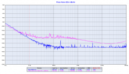
Next question.. It's my fault but where do I find the DDS generator spectra?
I attach the phase noise plot of the Rigol DDS generator at 200 kHz.
The cheap DDS generator performs around 8 dB better than the FifoPi at 10 Hz from the carrier, 25 dB better at 100 Hz and 20 dB better at 1 kHz.
But it is a losing battle, the measurements are not trusted in the opinion of the designer, since he claims that "It seems you are trying to degrade other's solutions by something that doesn't exist by now or not true".
I'm very stupid, I got an expensive gear to measure the phase noise while I could do better with a cheaper oscilloscope. Maybe I should have bought the Jitter package for my Lecroy WavePro 954, I would also have saved a lot of money.
Now I can figure out how stupid is Symmetricom (now Microsemi) who has bought the Timepod project from John Miles (the designer).
Attachments
@ andrea_mori
I'm discussing the measurement topic that you started. It seems you are trying to degrade other's solutions by something that doesn't exist by now or not true. So I have to post my point.
"I hope you are joking, -150dBc at 1 Hz"
The spurs were not the -150dBc. Could already be very close to 100dBc around 100Hz offset. I think you know what those spurs mean in the phase noise plot.
I respect your contribution to the oscillators to the community. But as an engineer, I have to tell the truth, if I see something that is not correct, I need to point it out.
After carefully reviewing your RPi jitter testing result I'm now more questioning about the accuracy of your SCK testing result.
1. RPi SCK has both random jitter and deterministic jitter, but your testing result didn't show any.
2. RPi SCK was from internal PLL, the jitter is in hundreds of ps levels, but your testing result was only RMS 9.843ps phase jitter @1Hz - 100KHz. That's very unreasonable. How did you make it?
Did you heavily filter all signals into sine waves when performing the measurement? If so, that will be not the case. A DAC uses the edges of i2S signals (not the sine wave) to operate. It will be meaningless If you don't measure the jitter of the edge, That's why I say phase noise is good for measuring oscillators but not good for digital signals.
No worry, I'll post my time domain jitter testing result the same as your conditions. Hopefully you can figure out why your testing results were not accurate.
Regards,
Ian
@Gerhard, thanks to explain that spurs have nothing to do with phase noise.
@Ian
I don't want to degrade your solutions, I have simply measured the phase noise performance with a suitable gear certified by Microsemi.
I have not filtered anything into sine wave, I have measured directly the square wave at the u.fl sockets of the FifoPi.
The Timepod also measure CMOS and other square-wave clocks.
Obviously you are free to publish your jitter results, I wonder what do you want to explain with a standalone number, but I look forward to know your explanation.
As I said your FifoPi is source dependent, as you know I have bought several boards from you and I have sperimented on my skin the sound difference changing the source.
This means that at least a part of the jitter from the source is not suppressed by the FIFO and the reclocker, and finally the noise reaches the output (or it's generated inside the FIFO).
The last time, your FIfoPi is a decent device at the right price, but it has nothing to do with state of the art devices, it's not the "ultimate" solution to remove the jitter.
If your measurements were not accurate, then everything you say will be incorrect.
By compared with my time domain measurements, I don't think your testing results are trustful. Seems you are trying to use inaccurate results to foolish all of us to promote your projects. That would be very unfair.
To telling the truth, I'll post my testing results to show what your testing results were wrong.
Regards,
Ian
Last edited:
@Gerhard, thanks to explain that spurs have nothing to do with phase noise.
@Ian
I don't want to degrade your solutions, I have simply measured the phase noise performance with a suitable gear certified by Microsemi.
I have not filtered anything into sine wave, I have measured directly the square wave at the u.fl sockets of the FifoPi.
The Timepod also measure CMOS and other square-wave clocks.
Obviously you are free to publish your jitter results, I wonder what do you want to explain with a standalone number, but I look forward to know your explanation.
As I said your FifoPi is source dependent, as you know I have bought several boards from you and I have sperimented on my skin the sound difference changing the source.
This means that at least a part of the jitter from the source is not suppressed by the FIFO and the reclocker, and finally the noise reaches the output (or it's generated inside the FIFO).
The last time, your FIfoPi is a decent device at the right price, but it has nothing to do with state of the art devices, it's not the "ultimate" solution to remove the jitter.
This story is truly curious.
When I did offer to measure your FifoPi (for free) you haven't even replied.
Then, when a kind member offer to send me his setup for measurement (in your place), you started to dispute the measurement method.
Finally, when the arrows for the bow are gone, you start disputing about the reliability of the instrument used for the measurements.
The published measurements are accurate and reliable, since they was done with a gear that costs around 10 times your oscilloscope.
You can buy a Microsemi 3120A (or a used Timepod if you find one, or else an Agilent E5052) to do the measurements yourself.
Until then you can't question the reliability of a $ 15,000 tool, because you are offending the reputation of John Miles (one of the smarter designer), Symmetricom, Microsemi and Microchip.
So if anyone wants to discredit something, that's you and not me.
Indeed I believe that with the profit you get selling your items you have enough room to buy a Timepod.
Well, I have nothing to promote, I'm not a business man like you, I'm here to share my projects and to help the audio community.
In fact I have never see any schematic, or PCB or BOM from you, only finished products to be assembled like LEGO.
Conversely I share my designs and often I lose money arranging group buy, while I also invest purchasing and building lab tools.
Our target (me and my co-developer) is a bit different from yours, we are developing a state of the art audio system for our use, we have no commercial interest, and we are glad to share our experience with the community.
We are hobbyist not businessmen.
I look forward to your measurements, but rather than continue to promise, please publish them.
I'm very curious, I would like to understand why you name "ultimate" your designs.
Andrea
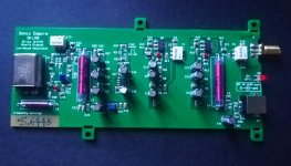
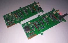
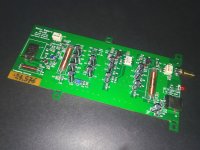
Back to the topic, some pictures of the finished Driscoll oscillators.
Oh this looks super nice, can’t wait for the bom and final measurements.
Just out of interest as the last picture also shows a casing, have you looked into shielding materials and do you have a distance recommendation as to speak how far is far enough from other equipment like psu, raspberries or DACs?
Mmh perhaps I have to build myself a rfi/emi sensor probe 😉
Last edited:
Hm. First of all, some weeks ago I have followed a sale of an 3120a on ebay. Finished unsold even after the final offer of 8000$, full software package included, NOS NIB, with guarantee.
I can imagine someone would have bought it for 6000/7000.
Last time I checked, only the jitter package cost ~10000$ for one of our Lecroy scope. Similar with Tek. Rhode Schwarz are more luxury priced.
I have a Tek on table in the lab, <<70000$.
Like a factory phase noise set from Keithley.
I find it not very good tasting, this bragging game..
It would be much much more useful remaining technical, and trying to be fully open, like in explaining in great details the tests executed.
Properly because a concurrent producer device is tested, without his approval, and without contacting him first.
Ciao, George
Oh this looks super nice, can’t wait for the bom and final measurements.
Just out of interest as the last picture also shows a casing, have you looked into shielding materials and do you have a distance recommendation as to speak how far is far enough from other equipment like psu, raspberries or DACs?
Mmh perhaps I have to build myself a rfi/emi sensor probe 😉
The box is a standard Hammond aluminum case, I will publish the item code from Mouser and Digikey.
I suggest to keep the oscillators far from other devices, at least 1 meter.
I suggest also to keep any other device as far as possible from the Raspberry.
Don't stack the devices.
- Status
- Not open for further replies.
- Home
- Source & Line
- Digital Line Level
- The Well Tempered Master Clock - Building a low phase noise/jitter crystal oscillator