Hi Andrea,
With the recent post of plots, are you now in a position to advise which circuit combos are likely to be best for a given application? I'd like to list my order.
Thanks for everything you are doing for us all!
-Raja
With the recent post of plots, are you now in a position to advise which circuit combos are likely to be best for a given application? I'd like to list my order.
Thanks for everything you are doing for us all!
-Raja
Last edited:
Hm. First of all, some weeks ago I have followed a sale of an 3120a on ebay. Finished unsold even after the final offer of 8000$, full software package included, NOS NIB, with guarantee.
I can imagine someone would have bought it for 6000/7000.
Last time I checked, only the jitter package cost ~10000$ for one of our Lecroy scope. Similar with Tek. Rhode Schwarz are more luxury priced.
I have a Tek on table in the lab, <<70000$.
Like a factory phase noise set from Keithley.
I find it not very good tasting, this bragging game..
It would be much much more useful remaining technical, and trying to be fully open, like in explaining in great details the tests executed.
Properly because a concurrent producer device is tested, without his approval, and without contacting him first.
Ciao, George
I have bought several boards from the designer, so I believe I'm free to measure what I have paid for, since the manufacturer does not provide any measurements.
I have offered to measure the FifoPi for free, see post Develop ultra capacitor power supply and LiFePO4 battery power supply
but the manufacturer has never replied.
I have explained the measurements, they was done with the 3 cornered hat technique using a Timepod 5330A, no filtering used, the incoming signals was attenuated 6dB as in any other measurement.
The measured phase noise of the square wave at MCLK output of the FifoPi is almost superimposable to the phase noise plot of the sine wave output from the oscillator used as the master clock for the FifoPi (Driscoll at 22.5792 MHz.)
This means that the measurement is reliable, there was only a little difference in the noise floor due to the noise added by the CMOS squarer (AC04).
For the last time, I'm not a competitor of the designer, I'm a hobbyist not an audio businessman, I have no commercial interest. The only interest for me arranging the group buy is to share the crystals MOQ imposed by the manufacturer, at least 10 pcs or more.
I have done the measurements to help the community, but if you are not interested you can simply forgot them.
As I said several time it would be very useful if the designer published his measurements, as I said I look forward to see them.
Finally, I'm seriously thinking to stop sharing our designs, since as I said we are designing the system for ourselves, not to start a business, and if every time I try to help the community I have to suffer the worst accusations (unreliable measurements, unfair competition and so on), better if I leave the scene.
I think discusssion is good as long as it doesn't get to emotional everyone can benefit from it. Let's just keep it technical anyone is free to make their own measurement believe or disbelief in measurements done by others. Accusations of fake /wrong measurements and distrust are never nice but they are everywhere in every technical field i guess. I think you are doing great service to a lot of people by sharing your findings and I appreciate it a lot. Perhaps you and ian should leave everything to their respective products/fields and anyone in the forum can take from the posted measurements whatever they want.
PS I have a fifopi and I like it a lot, as Andrea already said its a great product for its price so thanks to you too Ian 😉
Back to topic: would you think that some kind of "thermal shielding" to keep a constant temperature around the oscillator will give a better result? I was planning on doing such a thing but as you also disregarded the oven in this iteration I think it'd perhaps unnecessary.
Greetings oli
Hi Andrea,
With the recent post of plots, are you now in a position to advise which circuit combos are likely to be best for a given application? I'd like to list my order.
Thanks for everything you are doing for us all!
-Raja
I believe is better to wait until all device/combination have been measured. Next days we will measure the Differential oscillator (TWTMC-EXO) and the doublers.
I think discusssion is good as long as it doesn't get to emotional everyone can benefit from it. Let's just keep it technical anyone is free to make their own measurement believe or disbelief in measurements done by others. Accusations of fake /wrong measurements and distrust are never nice but they are everywhere in every technical field i guess. I think you are doing great service to a lot of people by sharing your findings and I appreciate it a lot. Perhaps you and ian should leave everything to their respective products/fields and anyone in the forum can take from the posted measurements whatever they want.
PS I have a fifopi and I like it a lot, as Andrea already said its a great product for its price so thanks to you too Ian 😉
Back to topic: would you think that some kind of "thermal shielding" to keep a constant temperature around the oscillator will give a better result? I was planning on doing such a thing but as you also disregarded the oven in this iteration I think it'd perhaps unnecessary.
Greetings oli
Temperature stability helps the long term stability of the oscillator, but since in audio we are looking for short term stability I would avoid the effort.
We have removed the oven because the phase noise plots with or without it was exactly superimposable, so better avoid more electrical and mechanical complications.
This is my last post about measurements, only because here someone is offending the reputation and the professionalism of people and manufacturers like John Miles and Microchip, that's unacceptable.
The Timepod 5330A (or the Microsemi 3120A) do reliable phase noise measurements of sine wave and CMOS/square wave clock signals, unless someone demonstrates the contrary.
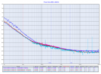
The first two plots validate the reliability of the measurements beyond any doubt.
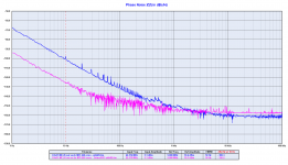
The first plot is the phase noise of the Driscoll oscillator at 22.5792 MHz (sine wave), while the second one is the phase noise plot of the same oscillator after squaring at the u.fl output of the FifoPi.
As you can see the two plots are almost superimposable, there is only a little difference above 3 kHz from the carrier, due to the noise added by the CMOS squarer.
As you know a square wave is a sine wave with infinite odd order harmonics, so the only issue measuring the phase noise of a square wave could be the noise of added by the harmonics, but since the bandwidth of the gear is 30 MHz even the 3rd order harmonic of a square wave at 22.5792 MHz does not cross the input filter (at 27 MHz).
The same about a 12.288 MHz square wave because the third harmonic is around 37 MHz and so it does not pass.
This means that even the phase noise measurement of a square wave at 12.288 MHz is absolutely reliable.
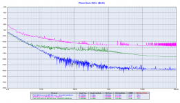
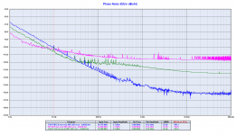
The third picture shows the phase noise plots of the Fifo MCLK output using the Driscoll oscillator, the RPI BCK output and the FifoPi SCK output, all are square wave signals correctly measured by the gear.
The phase noise (or jitter if you prefer) is not removed by the FifoPi, as you can see the phase noise of the SCK is 20 to 30 dB worse than the master clock. Only a part of the jitter coming from the RPI is removed, such 10-15 dB, but the most part such 20-30 dB is still present at the u.fl output of the FifoPi.
Now we can argue about the phase noise measurement of a square wave at 200 kHz, where some odd order harmonics could pass and affect the measurement.
When I will find the time I'll do a measurement with an input filter to understand if there is a difference.
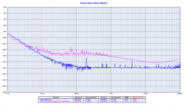
But even if we assume that the measurement was worse than the reality, looking at the 4th picture we can figure out the phase noise performance of the FifoPi LRCK.
If we assume the above we should shift down both the plots on the Y axis, I repeat BOTH plots and not only the FifoPi LRCK plot.
And this tells us that in any case the LRCK output of the FifoPi at 192 kHz has a phase noise 10 to 25 dB worse than a cheap Rigol DDS signal generator.
Keep in mind that this is the crucial clock to drive DAC like TDA1541A, AD1865, AD1862 and so on.
The fifth picture explains, at least in part the FifoPi LRCK phase noise, it's the LRCK clock captured with the oscilloscope. As you can see there is a clearly visible crosstalk, that's surely does not help the performance.
As you can see I keep always the discussion technical and I always try to motivate what I'm writing.
Please do the same
Andrea
The Timepod 5330A (or the Microsemi 3120A) do reliable phase noise measurements of sine wave and CMOS/square wave clock signals, unless someone demonstrates the contrary.
The first two plots validate the reliability of the measurements beyond any doubt.
The first plot is the phase noise of the Driscoll oscillator at 22.5792 MHz (sine wave), while the second one is the phase noise plot of the same oscillator after squaring at the u.fl output of the FifoPi.
As you can see the two plots are almost superimposable, there is only a little difference above 3 kHz from the carrier, due to the noise added by the CMOS squarer.
As you know a square wave is a sine wave with infinite odd order harmonics, so the only issue measuring the phase noise of a square wave could be the noise of added by the harmonics, but since the bandwidth of the gear is 30 MHz even the 3rd order harmonic of a square wave at 22.5792 MHz does not cross the input filter (at 27 MHz).
The same about a 12.288 MHz square wave because the third harmonic is around 37 MHz and so it does not pass.
This means that even the phase noise measurement of a square wave at 12.288 MHz is absolutely reliable.
The third picture shows the phase noise plots of the Fifo MCLK output using the Driscoll oscillator, the RPI BCK output and the FifoPi SCK output, all are square wave signals correctly measured by the gear.
The phase noise (or jitter if you prefer) is not removed by the FifoPi, as you can see the phase noise of the SCK is 20 to 30 dB worse than the master clock. Only a part of the jitter coming from the RPI is removed, such 10-15 dB, but the most part such 20-30 dB is still present at the u.fl output of the FifoPi.
Now we can argue about the phase noise measurement of a square wave at 200 kHz, where some odd order harmonics could pass and affect the measurement.
When I will find the time I'll do a measurement with an input filter to understand if there is a difference.
But even if we assume that the measurement was worse than the reality, looking at the 4th picture we can figure out the phase noise performance of the FifoPi LRCK.
If we assume the above we should shift down both the plots on the Y axis, I repeat BOTH plots and not only the FifoPi LRCK plot.
And this tells us that in any case the LRCK output of the FifoPi at 192 kHz has a phase noise 10 to 25 dB worse than a cheap Rigol DDS signal generator.
Keep in mind that this is the crucial clock to drive DAC like TDA1541A, AD1865, AD1862 and so on.
The fifth picture explains, at least in part the FifoPi LRCK phase noise, it's the LRCK clock captured with the oscilloscope. As you can see there is a clearly visible crosstalk, that's surely does not help the performance.
As you can see I keep always the discussion technical and I always try to motivate what I'm writing.
Please do the same
Andrea
Attachments
-
 Driscoll_225792_Sine.png105.4 KB · Views: 525
 -
 04 fifopi-mclk-crystek-24-576-_-driscoll-22-5792-mhz-phase-noise-png.png96.6 KB · Views: 522
 -
 05 rpi-fifopi-sck-driscoll-22-5792-mhz-phase-noise-png.png113.1 KB · Views: 510
 -
 Rigol DDS vs FifoPi LRCK.png79.2 KB · Views: 492
 -
 09 fifopi_lrck-jpg.jpg136.9 KB · Views: 510
The crosstalk could be through the grounds or simple EMI. My first thought are from experience is the long ago times tuning the clock tree on the CDC6600. Back then we had trim caps to adjust the clock delays as they propagate through the CPU. In this case I would add a d type flip flop clocked on the back edge of the clock to resync the Mclock/Bclock/Wclock/data to as clean a clock as available. When trying to get clean timing ground noise become a significant issue and less than a millivolt of noise can seriously degrade the timing moving the transition reference point. This is a real limitation in FPGA's and other LSI. Most DAC chips have internal reclocking to deal with this but they are only as good at the clocks and power supplies coming in.
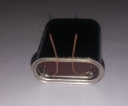
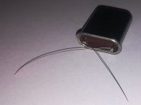
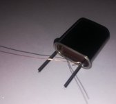
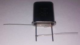
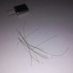
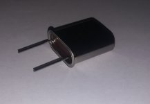
Andrea the oscillator board are superb,you did well to lay the crystal,the soldering by two small wire is against the vibrations I suppose,
Ian and Andrea shake hands it will be beneficial for everyone,
the love of good music brings us together.
Ian and Andrea shake hands it will be beneficial for everyone,
the love of good music brings us together.
Last edited:
Vibration can affect the close in phase noise (even air motion), so better if the crystal is decoupled.
You can use a thin strip of neoprene or foam with biadhesive on both side.
You can use a thin strip of neoprene or foam with biadhesive on both side.
Attachments
-
 IMG_20200420_173642.jpg82.8 KB · Views: 244
 -
 IMG_20200420_173154.jpg129.2 KB · Views: 226
 -
 IMG_20200420_172728.jpg84.8 KB · Views: 483
 -
 IMG_20200420_171857.jpg124.5 KB · Views: 476
 -
 IMG_20200420_171603.jpg88.1 KB · Views: 485
 -
 IMG_20200420_171229.jpg87.9 KB · Views: 492
 -
 IMG_20200420_171134.jpg68.4 KB · Views: 496
Great idea for vibration decoupling. I would never have thought of mounting the oscillator on foam with fine wires to decouple.
Your finished chassis could also be put in a larger box filled with sand.
Your finished chassis could also be put in a larger box filled with sand.
Questioning about andrea_mori's test results(1), Real RPi SCK time jitter measurement
I was hoping his phase noise testing results have much better accuracy. However it seems that both his SCK and LRCK phase noise/jitter testing results have big problems. I need to post my time jitter measurement result to let us figure out what was wrong.
I'll do the jitter measurements in the time domain under the same condition. Let's start from RPi SCK.
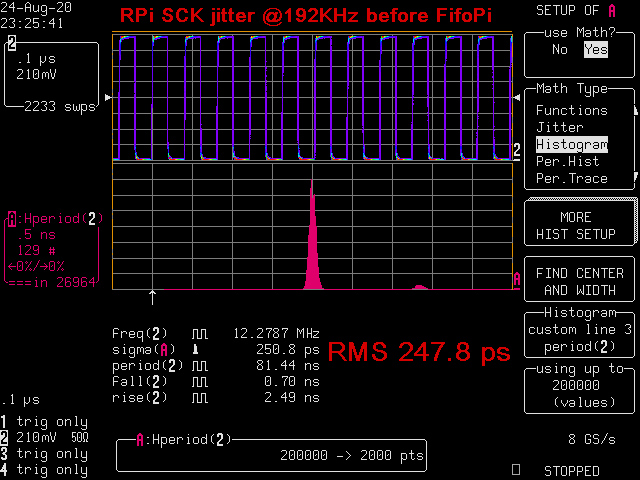
The first picture is the time jitter histogram plot of my RPi 4B SCK signal before FifoPi. I2S was running at 192KHz 32bit.
We can see clearly that there are both random jitter and deterministic jitter. The two deterministic jitter deltas separated in 1.7ns in between, one taller and one shorter, which were from the systematic jitter of RPi internal PLL (to generate audio clock)
The overall RMS jitter measured was 247.8ps .
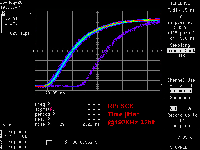
To make it easier to understand, I posted the second picture which is the direct jitter observation from my real time digital scope. The RPi SCK jitter is so big that it can even be seen directly from the waveform.
Both real random and deterministic jitter can still be figured out right away. (The 2.2ns rising time is also very slow), though it may not be as accurate as jitter histogram,
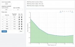
I attached andrea_mori's PPi SCK phase noise plot and phase to be compared. I see two problems with his testing results.
1. His phase noise plot didn't show any RPi SCK jitter signature in frequency domain (the pink curve). What was missing?
2. His RPi SCK phase jitter calculated was only RMS 9.843ps, far from the 247.8ps time jitter measurement. I don't think the measurement is reliable. Why can not see such a big jitter?
Seems his testing results can not tell what's the real jitter performance of a digital audio signal. I don't have a TimePod so I don't know what was wrong. But I think andrea_mori need to give us an explanation.
My testing condition:
LeCroy LC584 AXL real time high speed digital scope with jitter package running at 8GS/s
1GHz fully bandwidth without any filtering/limitation
Jitter measurement profile: period jitter histogram with RMS jitter calculation
real time jitter observation: Trigger at first raising edge, watch the following raising edge (79.95ns) (cycle to cycle jitter)
Jitter noise floor (2ps to 3ps)
SCK_RPi_192 by Ian, on Flickr
SCK_RPi_192_Direct by Ian, on Flickr
Regards,
Ian
This is my last post about measurements, only because here someone is offending the reputation and the professionalism of people and manufacturers like John Miles and Microchip, that's unacceptable.
The Timepod 5330A (or the Microsemi 3120A) do reliable phase noise measurements of sine wave and CMOS/square wave clock signals, unless someone demonstrates the contrary.
The first two plots validate the reliability of the measurements beyond any doubt.
The first plot is the phase noise of the Driscoll oscillator at 22.5792 MHz (sine wave), while the second one is the phase noise plot of the same oscillator after squaring at the u.fl output of the FifoPi.
As you can see the two plots are almost superimposable, there is only a little difference above 3 kHz from the carrier, due to the noise added by the CMOS squarer.
As you know a square wave is a sine wave with infinite odd order harmonics, so the only issue measuring the phase noise of a square wave could be the noise of added by the harmonics, but since the bandwidth of the gear is 30 MHz even the 3rd order harmonic of a square wave at 22.5792 MHz does not cross the input filter (at 27 MHz).
The same about a 12.288 MHz square wave because the third harmonic is around 37 MHz and so it does not pass.
This means that even the phase noise measurement of a square wave at 12.288 MHz is absolutely reliable.
The third picture shows the phase noise plots of the Fifo MCLK output using the Driscoll oscillator, the RPI BCK output and the FifoPi SCK output, all are square wave signals correctly measured by the gear.
The phase noise (or jitter if you prefer) is not removed by the FifoPi, as you can see the phase noise of the SCK is 20 to 30 dB worse than the master clock. Only a part of the jitter coming from the RPI is removed, such 10-15 dB, but the most part such 20-30 dB is still present at the u.fl output of the FifoPi.
Now we can argue about the phase noise measurement of a square wave at 200 kHz, where some odd order harmonics could pass and affect the measurement.
When I will find the time I'll do a measurement with an input filter to understand if there is a difference.
But even if we assume that the measurement was worse than the reality, looking at the 4th picture we can figure out the phase noise performance of the FifoPi LRCK.
If we assume the above we should shift down both the plots on the Y axis, I repeat BOTH plots and not only the FifoPi LRCK plot.
And this tells us that in any case the LRCK output of the FifoPi at 192 kHz has a phase noise 10 to 25 dB worse than a cheap Rigol DDS signal generator.
Keep in mind that this is the crucial clock to drive DAC like TDA1541A, AD1865, AD1862 and so on.
The fifth picture explains, at least in part the FifoPi LRCK phase noise, it's the LRCK clock captured with the oscilloscope. As you can see there is a clearly visible crosstalk, that's surely does not help the performance.
As you can see I keep always the discussion technical and I always try to motivate what I'm writing.
Please do the same
Andrea
I was hoping his phase noise testing results have much better accuracy. However it seems that both his SCK and LRCK phase noise/jitter testing results have big problems. I need to post my time jitter measurement result to let us figure out what was wrong.
I'll do the jitter measurements in the time domain under the same condition. Let's start from RPi SCK.
The first picture is the time jitter histogram plot of my RPi 4B SCK signal before FifoPi. I2S was running at 192KHz 32bit.
We can see clearly that there are both random jitter and deterministic jitter. The two deterministic jitter deltas separated in 1.7ns in between, one taller and one shorter, which were from the systematic jitter of RPi internal PLL (to generate audio clock)
The overall RMS jitter measured was 247.8ps .
To make it easier to understand, I posted the second picture which is the direct jitter observation from my real time digital scope. The RPi SCK jitter is so big that it can even be seen directly from the waveform.
Both real random and deterministic jitter can still be figured out right away. (The 2.2ns rising time is also very slow), though it may not be as accurate as jitter histogram,
I attached andrea_mori's PPi SCK phase noise plot and phase to be compared. I see two problems with his testing results.
1. His phase noise plot didn't show any RPi SCK jitter signature in frequency domain (the pink curve). What was missing?
2. His RPi SCK phase jitter calculated was only RMS 9.843ps, far from the 247.8ps time jitter measurement. I don't think the measurement is reliable. Why can not see such a big jitter?
Seems his testing results can not tell what's the real jitter performance of a digital audio signal. I don't have a TimePod so I don't know what was wrong. But I think andrea_mori need to give us an explanation.
My testing condition:
LeCroy LC584 AXL real time high speed digital scope with jitter package running at 8GS/s
1GHz fully bandwidth without any filtering/limitation
Jitter measurement profile: period jitter histogram with RMS jitter calculation
real time jitter observation: Trigger at first raising edge, watch the following raising edge (79.95ns) (cycle to cycle jitter)
Jitter noise floor (2ps to 3ps)
SCK_RPi_192 by Ian, on Flickr
SCK_RPi_192_Direct by Ian, on Flickr
Regards,
Ian
Attachments
Last edited:
Ian,
An interesting fact about jitter is the convertibility of it's presentation formats.
You could try it as well, by producing a very high sample batch, as much as max memory permits, perform a TIE trace extraction, and perform an FFT operation on the trace data.
That will provide a spectra which will show features very close to the phase noise plots of Andrea.
But worse quality. For several reasons: in the procedure to extract TIE values, an ideal clock stream has to be synchronized to the stream of data. This means a PLL algorithm is applied, with a pole usually at quite high frequency.
So your low frequency spectra information (close-in information) is cut off, truncated by the PLL.
Second, the sampling clock jitter of the scope itself is too high, generating a noise floor too high (in the zone close to the carrier)
You can not escape this limitation, the sampling clock is 8GHz.. It's noise floor is not comparable to the 5MHz reference clock in the TimePod spectra.
But, if You generate those FFT spectra, You will see that:
Random jitter is converted to noise floor 'shape' in the phase noise spectra;
Deterministic jitter is presented as discrete frequency spurs, sticking out of the noise floor;
Deterministic jitter magnitude is converted as height of the spurs.
So.
What You see in the phase noise plots of Andrea is the noise floor, the random jitter content of the Rpi clock. This You will never know how does it look like, because of the reasons above. There is no way to get at it with the scope.
Now there is a 'spur' supression function in the TimeLab software, that is probably used, and which kills the line related & other spur features as well.
The people who use these analysis tools, are usually more interested in the random floor evolution.
I do not totally share this thinking, I do think that deterministic jitter is important, especially if it is data correlated.
Another observation: your two peak jitter population are very unevenly distributed, means that apart from the main noise floor (first gaussian) there is only a very rarely present, (though far out) second family of edges..
That will only create a weak spur in any spectral presentation..
Ciao, George
Last edited:
perform a TIE trace extraction, and perform an FFT operation on the trace data. Ciao, George
Can Timelab pull TIE data from an HP5370 and generate the FFT you mentioned?
It would be interesting to see if there is data correlated jitter/phase noise in the system. No mention of whether there is active data, zero data or noise during these measurements.
Dear Demian,
I am afraid not.. TIE generation is complex fitting procedure on the scope data..
And yes, I have had very good times at looking those phase spectra extracted from my CD player SPDIF output stream, while in play, standby, stop .. at Diyhifi org. Quite educative.
Also looking directly at TIE trace itself, which is the waveform of the modulating signal which causes the jitter.
These things are what Andrea will never be able to enjoy, on the other side..
Ciao, George
Edit: Second thought: why not? I think the "frequency difference" plot is equivalent of the TIE trace plot; an FFT of that - - is the phase noise plot?
Last edited:
@Joseph K
Thanks, I think that's the reason why my digital scope has 2ps-3ps jitter measurement noise floor.
When I keep this sample rate for long time acquisition (measure jitter of low frequency signals, for example, 192KHz signal), this noise floor can be even higher.
Regards,
Ian
Thanks, I think that's the reason why my digital scope has 2ps-3ps jitter measurement noise floor.
When I keep this sample rate for long time acquisition (measure jitter of low frequency signals, for example, 192KHz signal), this noise floor can be even higher.
Regards,
Ian
Ian,
In the Lecroy I have access to - I could set the parameters (within limits) of the PLL routine.
In the function of sample length, it was possibble to force it in the low hundreds Herz region, maybe even lower, should look it up.
Maybe it's accessible also in yours?
Ciao, George
In the Lecroy I have access to - I could set the parameters (within limits) of the PLL routine.
In the function of sample length, it was possibble to force it in the low hundreds Herz region, maybe even lower, should look it up.
Maybe it's accessible also in yours?
Ciao, George
- Status
- Not open for further replies.
- Home
- Source & Line
- Digital Line Level
- The Well Tempered Master Clock - Building a low phase noise/jitter crystal oscillator