What's wrong with my interpretation of this datasheet? http://www.onsemi.com/pub_link/Collateral/74HC04.REV1.PDF
It says hex-inverter, the datasheet shows 6 inverters.... how come, that suddenly would be quite different? I think "if it sounds like a duck and looks like a duck, it probably is a duck..." So, why would reality be different from what the datasheet says?
C'mon man... you can do better than that
...page 4, figure 3
@alexiss: Might you have an opinion about using the Potsemi PO74 as an inverter in place of the 74HC... versions? Apparently they should return less noise to the surrounding PSU environment ...
Cheers,
Jesper
Cheers,
Jesper
It shows 3 sequential inverters (effectively functioning as one inverter), and says: 1/6th of the device shown. So what do I miss, the 74HCU04 datasheet? 😕C'mon man... you can do better than that
...page 4, figure 3
In my idea the discussion was about the 74HC04... so, did I go wrong there?
Last edited:
There is the mysterious logic diagram showing three gates in series inside. I had never seen that before either. I checked the Onsemi datasheet for a 74AC04 and it doesn't have that oddity either. There must be some aspect of the 74HC logic family thats atypical of the other CMOS families. 74HC does work down to 2V and that may be why its different. The AC input cap is 4.5 pF where the 74HC is 10 pF so effectively the 74AC has more "gain". 74AC is faster at around 4 nS vs the 74HC at 15 nS, but that may be the benefit- if the extra prop delay buys more isolation.
That is the benefit! The isolation is larger at lower supply voltages. The delay is very supply-line sensitive (introducing jitter) so that the power supply should be very clean!The 74AC is faster at around 4 nS vs the 74HC at 15 nS, but that may be the benefit- if the extra prop delay buys more isolation.
Herbert.
P.S.: I will investigate this subject more intensively in the coming weeks....
Last edited:
...The last stage with three in parallel is only for the low output impedance. With 30 ohm (I think by hart) in series the output impedance is 50 ohm, and .....
Herbert.
Hmmm...
Putting inverters in parallell to reduce output impedance is ill-advised in precision circuit design. Particularly in reference to ”jitter”.
Keep up the good work 🙂
Last edited:
@alexiss: Might you have an opinion about using the Potsemi PO74 as an inverter in place of the 74HC... versions? Apparently they should return less noise to the surrounding PSU environment ...
Cheers,
Jesper
Hej Jesper. Please look in your mailbox
Cheers.
There is the mysterious logic diagram showing three gates in series inside. I had never seen that before either.....
Unless specified otherwise (like 74HCU04), this is how virtually all standard
74-series of logic devices have been designed since the 70's, that is, complemented
by inverters - to function as so-called "buffers" - at every input and output...
Almost 40 years has passed, hopefully the designers know better...
cheers
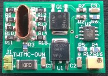
Waiting for SC-Cut crystals, the oven is ready.
It keeps the crystal at a constant temp around 82°C.
It keeps the crystal at a constant temp around 82°C.
Attachments

Last edited:
Waiting for SC-Cut crystals, the oven is ready.
It keeps the crystals at a constant temp of about 82°C.
Sweet. I can't wait to try it myself. It looks great.
Waiting for SC-Cut crystals, the oven is ready.
It keeps the crystal at a constant temp around 82°C.
Nice one Andrea, expect a more refined finish of the copper case for better thermal conduction.
Last edited:
Nice one Andrea, expect a more refined finish of the copper tube for better thermal conduction.
The tube that fits the crystal is made starting from a round copper pipe for conditioning and pressing it using a vise.
To get better refined result it should be made by a milling machine starting from a copper solid bar.
I have asked some manufacturers, but they ask high MOQ and high price.
I attach the drawing of the copper tube, all dimensions are in mm.
Maybe someone could ask his local manufacturer to get a quote.
Attachments
Last edited:
The tube that fits the Crystal is made starting from a round copper pipe for conditioning and pressing it using a vise.
To get better refining result it should be made by a milling machine starting from a copper solid bar.
I have asked some manufacturers, but they ask high MOQ and high price.
I attach the drawing of the copper tube, all dimensions are in mm.
Maybe someone could ask his local manufacturer to get a quote.
I may be able to help on this.
Andrea please check PM
Last edited:
Waiting for SC-Cut crystals, the oven is ready.
It keeps the crystal at a constant temp around 82°C.
Is an oven really necessary for a low jitter oscillator?
It keeps the crystal at a constant temp around 82°C.
Why should you? The absolute frequency is not important at all!!!! A frequency deviation of even 1000 ppm is not detectable for the human ear.
Now this gets complex-
The SC crystals flat temp-freq response range is around 80c. At room temperature it changes frequency more than an AT cut.
Crystal ovens are really much more complex and involved than this implementation. There is a whole art to temperature stability and they get better than .1c stability, sometimes much better with double ovens and very carefully controlled "leaks" etc. This will get the crystal to a good enough temperature.
If the goal is low close in noise the frequency shifts from small temperature shifts are exactly what you need to avoid. Absolute accuracy is not needed for audio, just short term stability (ppb per hour).
The higher Q of an SC crystal should have lower phase noise which is the justification of this effort.
Why should you? The absolute frequency is not important at all!!!! A frequency deviation of even 1000 ppm is not detectable for the human ear.
SC-Cut crystals are calibrated to operate at high temp, since their inflection point is around 80-90°C. Although in audio we don't care about absolute frequency and long term stability, I don't know if using an SC-Cut crystal at lower temp (say ambient temp) affects the short term stability and the phase noise of the oscillator.
BTW, everyone is free to use SC-Cut crystal with or without the oven. The oven is a separate board that fits the crystal of the Driscoll oscillator.
Last edited:
I don't know if using an SC-Cut crystal at lower temp (say ambient temp) affects the short term stability and the phase noise of the oscillator.
But I know: it does not !
The higher Q of an SC crystal should have lower phase noise which is the justification of this effort.
... should have.... but the Rm is at least 5x higher so that the power used must be at least 5x lower!
- Status
- Not open for further replies.
- Home
- Source & Line
- Digital Line Level
- The Well Tempered Master Clock - Building a low phase noise/jitter crystal oscillator