Better and easier would be to replace one of the caps around the crystal with a varicap diode and feed it white noise. The HF limit may be about 10 KHz for this to work but it does work very well. You can replace C1 with a varicap diode, cathode connected to the crystal end, connect it to an external DC supply to reverse bias it with 1K resistor for isolation. Couple the modulation into it via the resistor. You can calibrate the frequency shift my measuring the shift with a counter for a DC voltage. I would not expect more than maybe 10 Hz with an AT crystal. An SC would be more like 1-2 Hz. This is also a good way to dial the frequency to your target if you have the necessary equipment. What you would have is a VXCO.
Another option is to tie it to a PLL to lock to an external clock (E.G. the one coming from an SPDIF receiver) to lock and clean that clock. Probably not too useful with the latest generation of SPDIF receivers, they are already really good.
Another option is to tie it to a PLL to lock to an external clock (E.G. the one coming from an SPDIF receiver) to lock and clean that clock. Probably not too useful with the latest generation of SPDIF receivers, they are already really good.
@1audio: Hi ... Taking a slight detour here but hope it's ok ...
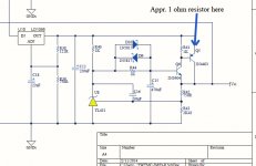
Can I ask you to just quickly verify (I am about to order components) that this would be the place to current limit the PSU circuit used for the TWTMC-D&D? It looks as if a 1 ohm resistor could be placed on the emitter of the 2N4403 - and thus limit the current to about 0.6A (pls see attachment). But maybe there's a better way of doing this?
Thanks for any help ;-)
Jesper
Attachments
... ouups ... I think the current limiting suggestion I posted yesterday won't work so please disregard my question ...
Cheers,
Jesper
Cheers,
Jesper
If you'd parrallel the 1k resistor with two diodes (and adding a resistor in the Collector-leg of the transistor Q6), it would...... ouups ... I think the current limiting suggestion I posted yesterday won't work so please disregard my question ...
Cheers,
Jesper
Last edited:
* * * * * * * * * * * * * * * * * * * * * * * * * * * * * * * * * * * * * * * * * * * * * * * * * *
Hej Jesper og takk for the vote of confidence.
All commercially available Master Clocks have one thing in common:
They over-promise and under-deliver, and none provide measurements (except for Tent-clock at 33 MHz)... It is VERY difiicult to find a good Master Clock for audio applications these days.
For this reason, Andreas efforts are much appreciated.
It is not my intention to be a "smart-***" and provide a list of improvements to Andreas design. That is why I asked him to revise the design (I'm not sure he's got the time though).
If you look carefully, I did mention something in the previous post.
Without digging too deep, there are many ways to lower the DL, some very simple and some a bit more complex.
But any modification (even good ones) to the present circuit will result in - you guessed it: altered phase noise figures.
Therefore it should be done by the designer and verified through measurement. So you see, it is not as simple as saying: remove this or change that....
Andrea has provided measurements for the present TWTMC design, so please stick with it and make no changes (without consulting the designer or verifying it through measurement).
I believe he is working on a simplified Driscoll design that will be interesting.
The original Driscoll has the highest short-term stability of harmonic-type designs that I've encountered, and I think it will accommodate even AT resonators (with some minor component value changes).
This design is also more forgiving about DLs and so forth, so lets wait and see...
cheers...
There is a simple way to decrease the drive level, tie the schottky to a negative rail, say -1.2/-1.5V, maybe using a battery. The current flowing through the crystal falls down to 5-6mA. But there are a couple of drawbacks. Firstly we need a very low noise reference voltage, since we are injecting noise in the gate circuit. Batteries are noisy, we could use an LC filter, but I believe the phase noise increases anyway.
Moreover the output voltage of the oscillator decreases down to around half of the current voltage swing, increasing again the phase noise.
Other solutions are complex and require a totally new design with different layout.
As you pointed out I have limited time to spend around this project, so at this time I prefer to work around the emitter coupled oscillator.
Maybe in the future...
Hello everyone ... ;-)
@esgigt:
Thanks for the tip! I've tried it out today and using 1N914 diodes and a 10 ohm resistor on the emitter I get what to me is a satisfactory balance between current limiting, low voltage difference/current draw, and a reasonably well-defined current limiting point.
Merci encore!
@alexiss:
Hi Alexiss,
Well, you're welcome ... Thanks to you also for following up & replying 😉
When I read your post I had the impression that you knew about oscillators and possibly because I have partly been "brought up" with one of the first companies here in Denmark adopting the so-called "learning organization" I tend to pick up when people have ideas or knowledge and ask about it ... Thinking something constructive and useful may come from this ...
As it is I'm gaining interest in the AT/SC-cut driscoll version and also look forward to seeing what Andrea arrives at ....
My thoughts as well,
🙂 Jesper
P.S.: I'm considering doing a bit of advertising in the forum for the 6.144 MHz version so that it may be possible to get one - should some of you be interested ...
@esgigt:
If you'd parrallel the 1k resistor with two diodes (and adding a resistor in the Collector-leg of the transistor Q6), it would...
Thanks for the tip! I've tried it out today and using 1N914 diodes and a 10 ohm resistor on the emitter I get what to me is a satisfactory balance between current limiting, low voltage difference/current draw, and a reasonably well-defined current limiting point.
Merci encore!
@alexiss:
Hej Jesper og takk for the vote of confidence.
All commercially available Master Clocks have one thing in common:
They over-promise and under-deliver, and none provide measurements (except for Tent-clock at 33 MHz)... It is VERY difiicult to find a good Master Clock for audio applications these days.
For this reason, Andreas efforts are much appreciated.
It is not my intention to be a "smart-***" and provide a list of improvements to Andreas design. That is why I asked him to revise the design (I'm not sure he's got the time though).
Hi Alexiss,
Well, you're welcome ... Thanks to you also for following up & replying 😉
When I read your post I had the impression that you knew about oscillators and possibly because I have partly been "brought up" with one of the first companies here in Denmark adopting the so-called "learning organization" I tend to pick up when people have ideas or knowledge and ask about it ... Thinking something constructive and useful may come from this ...
As it is I'm gaining interest in the AT/SC-cut driscoll version and also look forward to seeing what Andrea arrives at ....
For this reason, Andreas efforts are much appreciated.
My thoughts as well,
🙂
JesperP.S.: I'm considering doing a bit of advertising in the forum for the 6.144 MHz version so that it may be possible to get one - should some of you be interested ...
. . . . . Other solutions are complex and require a totally new design with different layout.
As you pointed out I have limited time to spend around this project, so at this time I prefer to work around the emitter coupled oscillator.
Maybe in the future...
Hello Andrea and thank you for your response.
What you just mentioned is one of the main reasons why I have stayed away from Colpitt-type oscillators for low frequency.
They are the "sole rulers" of RF class of oscillators, specially SHF, but for low frequency design, I would much prefer the one you are presently working on i.e. the Driscoll type. I am sure you will achieve excellent results with it.
Playing with one a while back, I recall the Q of the circuit being so high, the simulator we had back then would not converge without comprehensive manipulation of start-up conditions and massively lowering the In-Circuit Q. Now that's a very good sign.
The Driscoll circuit + the very nice SC-C crystal you have in hand might just become the best MCK oscillator for audio to date.
I'll be looking forward to seeing the measurements. Good luck!
Last edited:
Hello everyone ... ;-)
@alexiss:
Hi Alexiss,
... As it is I'm gaining interest in the AT/SC-cut driscoll version and also look forward to seeing what Andrea arrives at ....
My thoughts as well,
🙂
P.S.: I'm considering doing a bit of advertising in the forum for the 6.144 MHz version so that it may be possible to get one - should some of you be interested ...
Hej Jesper.
Yes, Andrea's Driscoll oscillator will be interesting, specially since he has the capability to perform measurements on it.
I recall looking (a few years back) at some documents showing measurements on identical oscillator circuits with AT-C vs SC-C crystals.
The SC-C had of course vastly superior performance at higher offset frequencies, but they were equal at lower offsets from the carrier.
Many believe this to be very important for Audio since audio is a low frequency phenomenon.... I am not sure if this is valid... let's just wait for Andreas results.
Glædelig jul og et godt nyt år til dig.
Hej Alexiss,
Interesting with the AT-cut & SC-cut differences between close and far from the carrier frequency. Personally I tend to believe in the relevance of the close-to-carrier frequency stability - possibly with a basis in my experiments in the late nineties with stabilizing the rotational speed of a turntable I had built. It made quite a difference.
I observed a somewhat similar phenomenon when I shifted to low phase noise XOs - so I have a belief in this although I don't know where the limit for audibility is. This, however, I also guess depends much on the quality of the evaluation system - and the "mental tranquility" of the person listening.
God jul och ett gott nytt år också till dig 🙂
Jesper
Where did you get the idea that batteries are noisy? NiCds are about as noise-free asFirstly we need a very low noise reference voltage, since we are injecting noise in the gate circuit. Batteries are noisy, we could use an LC filter, but I believe the phase noise increases anyway.
it gets.
< http://www.hoffmann-hochfrequenz.de/downloads/NoiseMeasurementsOnChemicalBatteries.pdf >
or search for "Walls NIST time frequency group chemical batteries", 1033.pdf
I'm not sure about the filename. He had to build a measurement system that
goes down to -205dBV.
regards, Gerhard
Where did you get the idea that batteries are noisy? NiCds are about as noise-free as
it gets.
< http://www.hoffmann-hochfrequenz.de/downloads/NoiseMeasurementsOnChemicalBatteries.pdf >
or search for "Walls NIST time frequency group chemical batteries", 1033.pdf
I'm not sure about the filename. He had to build a measurement system that
goes down to -205dBV.
regards, Gerhard
I remember a test published by Thorsten Loesch where batteries (I don't remember what type) performed noisier than a commercial regulator (TL431 if I remember correctly), above all at low frequencies.
I would prefer the schottky tied to ground rather than to a voltage rail, but if someone was interested to try this way, the power dissipated in the crystal decreases to around 350 uW in case of 45 and 49 MHz crystals, to around 140 uW in case of 22/24 MHz, to around 200 uW for the 11 MHz, and also the output voltage decreases to 1-1.5V pp. More safely if we care of crystal aging.
Andrea
Regarding batteries and noise. From my experience as electronics engineer batteries are one of the most low-noise components available. Their noise are basically determined by the thermal noise of the internal resistance(which is usually very low) + 1/f noise. Yes, you can design regulators that have less noise, but it will most likely take much more effort and more iterations than just using batteries.
I have found a paper where they measure noise on chemical batteries. According to their results the noise density for good batteries are lower than 1 nV/SQ(Hz) for frequencies over 100 Hz. This is better than for example ADM7150 from Analog devices where the noise density never goes below 1.5 nV/SQ(Hz)
Link to the paper:
http://www.hoffmann-hochfrequenz.de/downloads/NoiseMeasurementsOnChemicalBatteries.pdf
ADM7150 datasheet:
http://www.analog.com/media/en/technical-documentation/data-sheets/ADM7150.pdf
Thanks Gerhard and Gunders for a good reference document. Very interesting measurement results.
I never thought of NiCad batteries as such low noise sources.
At the risk of further elaboration on the xtal DL, it might be interesting to many of fellow diy members here to remember that the TWTMC is a parallell-mode xtal oscillator, running the xtal off-series resonance point.
This would allow for higher xtal dissipation than at exatct series resonance (where the Driscoll operates).
But a good bias-point would be to keep the dissipation around 50 uW for the resonator. With that in mind, there are other ways of reducing the DL but lets leave it alone.
Any modification will alter the phase-noise characteristics of the circuit which Andrea has provided measurement for.
The Driscoll oscillator is a much better performer (xtal placed at low-power point, signal taken at high power-point) and it can be adjusted to accomodate the AT-C variants. Lets wait for this one.
My ideal would be the Driscoll AT-C at 11.2896MHz with carefully designed peripherals.
Good luck.
...cheers
Last edited:
I'm just wondering. What measurement equipment would be the "best" to test the oscillator's performance and which parameters are important?
I guess that something like a R&S FSV Signal and Spectrum Analyzer with a FSV-K40 Phase Noise Measurements module would be more or less perferct?
Unfortunately I don't have access to a good spectrum analyzer, but we have a R&S ZNC Vector Network Analyzer. Can it somehow be used to measure the performance of a oscillator?
A VNA is not the right tool for that measurement. There are a handful of really good tools, most in the $30K+ range. With patience a DIY'er could build a test set that could do a good job when used with a soundcard. Ideally you would need two good oscillators with voltage controlled inputs (maybe Crystek?) two good mixers (Minicircuits would be good enough) and software (HPworks has the right capabilities). Still not cheap at probably $150-$250.
That is mine. Counts only one time.
The NIST paper, with even lower demonstrated limits:
< http://tf.nist.gov/timefreq/general/pdf/1133.pdf >
That is mine. Counts only one time.
The NIST paper, with even lower demonstrated limits:
< http://tf.nist.gov/timefreq/general/pdf/1133.pdf >
Hi Gerhard,
Yes, it's actually your paper. I wasn't aware of that. Nice work.
I have also looked at the paper you have linked to, it is interesting but I found it a bit hard to distinguish the different batteries in the plots. But in general it shows that the noise density from batteries are low.
LiFePO4
Gerhard,
Have you had occasion to test the noise of these batteries? I believe their internal resistance is lower than NiCd cells.
Regards,
George
Gerhard,
Have you had occasion to test the noise of these batteries? I believe their internal resistance is lower than NiCd cells.
Regards,
George
Have you had occasion to test the noise of these batteries? I believe their internal resistance is lower than NiCd cells.
I'm interested, too, but would not like to buy one just for testing. Maybe when
the Pb battery of my bike fails next time. Just got a new one 6 weeks ago 🙁
Just €150 at your friendly BMW store...
Btw I came to this DC noise testing when an oscillator of mine showed a
noise molehill at 400 KHz offset.
Last edited:
The A123 cell is available at A123 Systems Online Shop | Distrelec Schuricht Germany for €11.50. If you have the time to test it, I'll pay for the cell. 🙂
George
George
- Status
- Not open for further replies.
- Home
- Source & Line
- Digital Line Level
- The Well Tempered Master Clock - Building a low phase noise/jitter crystal oscillator