Andrea what abour "owenized" boards? Did You try maybe?
I'm looking for a suitable copper oval tube to solder to the board and fits the crystal (internal size 3.5mmx10mm, wall thickness <1mm), then I'll order the PCB heater prototype.
Hi Andre,
How does the 1st MO crystal measure at 1hz (phase noise) or compare with the crystek crystals?
I am rather lost on the ocxo's, thee are not drop in and how do we implement it into a vcxo circuit? A board (PLL?) Is need to covert the ocxo sine wave output to squarewave before it is used, if i am correct. I presume that implementationof the ocxo will have better phase noise than the drop in crystals?
These boards are still in progress before confimation can be made that it's a go with the ocxo, interested! so a power supply for the ocxo heater and PLL has tp be added in order for the ocxo to work.
Will a circuit be reserved that allows a 10m reference be included for the next stage project after the ocxo?
Last edited:
Hi Andre,
How does the 1st MO crystal measure at 1hz (phase noise) or compare with the crystek crystals?
I am rather lost on the ocxo's, thee are not drop in and how do we implement it into a vcxo circuit? A board (PLL?) Is need to covert the ocxo sine wave output to squarewave before it is used, if i am correct. I presume that implementationof the ocxo will have better phase noise than the drop in crystals?
These boards are still in progress before confimation can be made that it's a go with the ocxo, interested! so a power supply for the ocxo heater and PLL has tp be added in order for the ocxo to work.
Will a circuit be reserved that allows a 10m reference be included for the next stage project after the ocxo?
I have not yet measured the phase noise of the Colpitts-Clapp oscillator. As I said, I have limited access to a university lab, so I will measure all the 3 oscillators (Clapp, Butler and Driscoll) when they will be all ready. For now you can refer to the plot I posted in #5, where the the Clapp oscillator was measured using a similar crystal.
About the SC-cut crystal, I'll not provide any PLL. These crystals could be also used in the Clapp oscillator, while I'll start experimenting soon with Butler 2 emitters and Driscoll oscillators, more suitable for high Q crystals, since the crystal sees a very low impedance, that means very high loaded Q.
Next weeks I'll order the crystal heater PCB (#515). It could be used with all the 3 oscillators. The power supply for the heater will be taken from the daughter board.
Now I have to ship the first batch items to all the members, on next tuesday.
Now I have to ship the first batch items to all the members, on next tuesday.
😀
BOMs?
//
I have not yet measured the phase noise of the Colpitts-Clapp oscillator. As I said, I have limited access to a university lab, so I will measure all the 3 oscillators (Clapp, Butler and Driscoll) when they will be all ready. For now you can refer to the plot I posted in #5, where the the Clapp oscillator was measured using a similar crystal.
About the SC-cut crystal, I'll not provide any PLL. These crystals could be also used in the Clapp oscillator, while I'll start experimenting soon with Butler 2 emitters and Driscoll oscillators, more suitable for high Q crystals, since the crystal sees a very low impedance, that means very high loaded Q.
Next weeks I'll order the crystal heater PCB (#515). It could be used with all the 3 oscillators. The power supply for the heater will be taken from the daughter board.
Now I have to ship the first batch items to all the members, on next tuesday.
The sc crystal are drop in replacements, am i correct, but can be used to obtain better noise with the clapp oscillator circuit.
Will the connections be simple with the daughterboard. Power and it will output a 3.3v squarewave.
Thanks
The sc crystal are drop in replacements, am i correct, but can be used to obtain better noise with the clapp oscillator circuit.
Will the connections be simple with the daughterboard. Power and it will output a 3.3v squarewave.
Thanks
Yes, you can use SC-cut crystal with the Clapp oscillator to get 3V3 square wave and (theoretically) better phase noise.
Connections with daughter board are the same for power supplies.
Both heaters have to be connected to the DC header of the daughter board with separate wires. The heater board fits the crystal of each XO.
Maybe, the transformer has to be replaced with a 12VA type.
Andrea-
I think your first explorations in making an oven will be quite interesting. making an oval copper tube should be pretty easy with a vise. But getting it temperature stable and not melting everything around it is a different issue. The oven will need to operate at over 70C so it will radiate a lot of heat if you don't have good insulation around it and finding the optimum temperature is a unit to unit effort. Typically OXCO's have very carefully designed insulation and heat loss paths. Too much insulation and stability of the oven becomes a problem. The better ovens use a PID controller etc. and double ovens. I don't think that is necessary in this application.
This artiucle will give some broader insight into OXCO's: http://www.vectron.com/products/appnotes/ocxo.pdf
Andrea-
I think your first explorations in making an oven will be quite interesting. making an oval copper tube should be pretty easy with a vise. But getting it temperature stable and not melting everything around it is a different issue. The oven will need to operate at over 70C so it will radiate a lot of heat if you don't have good insulation around it and finding the optimum temperature is a unit to unit effort. Typically OXCO's have very carefully designed insulation and heat loss paths. Too much insulation and stability of the oven becomes a problem. The better ovens use a PID controller etc. and double ovens. I don't think that is necessary in this application.
This artiucle will give some broader insight into OXCO's: http://www.vectron.com/products/appnotes/ocxo.pdf
Demian,
thanks for the link.
Firstly I thought to use epoxy resin to coat the copper tube and the crystal. But in this way the crystal is completely closed and so I have difficult to measure the temp to tuning the heater circuit.
I will leave all open, maybe I could use some thermal paste between the crystal and the tube walls. Operating temperature will be around 80°.
As you, I think some temp drift is not an issue for digital audio application.
Maybe this will help or give you some ideas:
http://www.karlquist.com/osc.pdf
http://www.karlquist.com/oven.pdf
http://www.karlquist.com/osc.pdf
http://www.karlquist.com/oven.pdf
Attachments
Last edited:
Ovens are for satellites and base stations on roof tops exposed to great temperature variation with a lifespan of 30 years (old design requirement . obsolete today...). Guess this oven will probably help most by isolating the crystal from the sound pressure in the room - nothing bad with this , rather the opposite. The temp variation is not an issue in most implementations. Nor do we need the long term aging compensation as in next years, MEMS will the latest scheisse 🙂
//
//
I'm looking for a suitable copper oval tube to solder to the board and fits the crystal (internal size 3.5mmx10mm, wall thickness <1mm), then I'll order the PCB heater prototype.
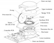
Andrea,
I've had a look inside a few OCXO's that I have used and they had a flat
heating element mounted on pcb with the XO can bonded directly to it. It
seems like a decent system. You could perhaps even sandwich the XO can
between the main pcb and a small top pcb to get better heating efficiency.
The heating elements can be smt 2512 high temp resistors with some small
mica washers to prevent shorting on the can.
Refer to the CAD pics.
cheers,
Attachments
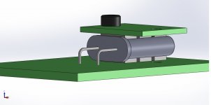
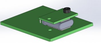
Heater
Thanks all for the suggestions about the oven.
I'll start experimenting soon.
But keep in mind we are not building an OCXO for satellite communication. Some long term frequency deviation is not an issue in digital audio.
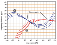
Take a look at the attached image: optimum working temperature for SC-cut crystal is around +85°, but a variation between +50° to +100° gives a deviation of 3-4 ppm.
Thanks all for the suggestions about the oven.
I'll start experimenting soon.
But keep in mind we are not building an OCXO for satellite communication. Some long term frequency deviation is not an issue in digital audio.
Take a look at the attached image: optimum working temperature for SC-cut crystal is around +85°, but a variation between +50° to +100° gives a deviation of 3-4 ppm.
Attachments
Thanks all for the suggestions about the oven.
I'll start experimenting soon
As I remember, from the old days, Elektor had some project ...
Hp
Since low phase noise at 1 Hz is a goal the thermal mass should be large enough to slow the change to reduce the phase noise impact from a temperature change. Done right it would also reduce the vibration sensitivity.
What events or entities could affect the temperature and at what rate of change can we anticipate?
Inside a typical DAC box temperature should be stable. What can happen?
//
Inside a typical DAC box temperature should be stable. What can happen?
//
Exactly - hence my simple suggestion.Thanks all for the suggestions about the oven.
I'll start experimenting soon.
But keep in mind we are not building an OCXO for satellite communication.
Also agreed, you have a larger temperature range to play with so theSome long term frequency deviation is not an issue in digital audio.
Take a look at the attached image: optimum working temperature for SC-cut crystal is around +85°, but a variation between +50° to +100° gives a deviation of 3-4 ppm.
advantage is the temp adjustment (feedback) control can be very slow at
deficit of some temp drift which doesn't matter for this app.
I've specced OCXO's for audio apps in the past and it can get interesting
liaising with the applications engineer, they often initially scratch their head
and think you're an idiot until you fully explain to them what's driving your
odd design specs. That's audio 🙂
Since low phase noise at 1 Hz is a goal the thermal mass should be large enough to slow the change to reduce the phase noise impact from a temperature change. Done right it would also reduce the vibration sensitivity.
SC-cut crystals are reportedly less sensitive to vibrationally induced phase
noise but there seems to be conflicting information about that. Regardless, it's
probably worth trying some additional mass together with isolation.
Whether that means isolating the whole board or just where crystal is, is
another question. I know when I used to be involved with audio tweakaholics,
people used to report various amounts of bluetac on a CD players /
transports crystal made sonic differences.
Recipe:
- Glass sphere 10 cm, with nipple outlet, in half.
- Clock-board with metallic foundation.
- Clock board with laser transmitter
- Clock board with inductive receiver
- Clock board inside glass sphere.
- Make clock board levitate inside sphere by outside magnet.
- Evacuate air to as close as vacuum possible.
- Power feed clock board via induction (solar panel OK also?)
- Receive clock via laser (is radio better?)
Enjoy stable clock 🙂
//
Last edited:
- Status
- Not open for further replies.
- Home
- Source & Line
- Digital Line Level
- The Well Tempered Master Clock - Building a low phase noise/jitter crystal oscillator