eduard
FWIW, I replaced split bobbin transformers with the Plitron transformer in the DAC and received improved sound. I think there is more to the Plitron design than the screen.
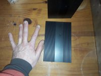
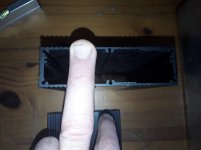
I have commented on the SMA vs solder of the bulk head cable. I think the issue is more to do with durability than performance. I covered the durability issue by running it through the wood. When I receive the SMA terminated cable I'll test for sound impact and report.
I think Andrea's approach of using thin wires to attach the crystal is excellent. Which is why I did the same.
I agree that isolating the crystal from the pcb is a great idea. I put the crystal entirely within foam. It's only connection to anything is the thin wire that makes the electric connection. The foam that the pcb rests on is weighted down by a 1/2" layer of sand in a zip lock bag. Again I have had good success with this approach. Compared to springs, rubber grommets or hanging by thin threads, sand always outperformed in my observation.
There are many different ways to achieve these goals. My point is simply that FWIW, gains in isolation are rewarded by subjective improvement in sound. I suspect vibration can be as simple as the feedback loop from the speakers back to the chassis.
In any event, I think its worthwhile to play around with this stuff and be creative. A challenge.. One experiment that would be easy is:
Build your WTMC in the specified chassis. Once its burned in and you know the sound well, put the chassis in a plastic bag into a slightly bigger box and bury it in sand. The sand should be under and around the whole thing. I use the stuff sold to fill in the cracks on interlocking bricks. Its fine and dry. Then tell us if you do or do not hear the difference. The BOM is a shoe box, a plastic bag, and a bag of sand. 🙂
FWIW, I replaced split bobbin transformers with the Plitron transformer in the DAC and received improved sound. I think there is more to the Plitron design than the screen.
I have commented on the SMA vs solder of the bulk head cable. I think the issue is more to do with durability than performance. I covered the durability issue by running it through the wood. When I receive the SMA terminated cable I'll test for sound impact and report.
I think Andrea's approach of using thin wires to attach the crystal is excellent. Which is why I did the same.
I agree that isolating the crystal from the pcb is a great idea. I put the crystal entirely within foam. It's only connection to anything is the thin wire that makes the electric connection. The foam that the pcb rests on is weighted down by a 1/2" layer of sand in a zip lock bag. Again I have had good success with this approach. Compared to springs, rubber grommets or hanging by thin threads, sand always outperformed in my observation.
There are many different ways to achieve these goals. My point is simply that FWIW, gains in isolation are rewarded by subjective improvement in sound. I suspect vibration can be as simple as the feedback loop from the speakers back to the chassis.
In any event, I think its worthwhile to play around with this stuff and be creative. A challenge.. One experiment that would be easy is:
Build your WTMC in the specified chassis. Once its burned in and you know the sound well, put the chassis in a plastic bag into a slightly bigger box and bury it in sand. The sand should be under and around the whole thing. I use the stuff sold to fill in the cracks on interlocking bricks. Its fine and dry. Then tell us if you do or do not hear the difference. The BOM is a shoe box, a plastic bag, and a bag of sand. 🙂
Last edited:
I have commented on the SMA vs solder of the bulk head cable. I think the issue is more to do with durability than performance. I covered the durability issue by running it through the wood. When I receive the SMA terminated cable I'll test for sound impact and report.
from an impedance integrity point of view, a connection like that is a carnage 🙂
great efforts was done in order to keep the impedance controlled all over the board... it's a pity to mess it up right at the output.
then... if you hear a difference, i don't know...
I'll take your word for it.
Hard to understand given it looks pretty identical to the sma connection to the pcb, but I'll replace it in due time.
Hard to understand given it looks pretty identical to the sma connection to the pcb, but I'll replace it in due time.
I also think that the biggest source of vibration is the coaxial cable and that of power,
A first insulation is obtained by placing the set on a shelf on the wall,I will put the board in the Hammond housing suggest by Andrea,then the two Hammond in Modushop enclosure Slim Line 01/280 1U 4mm ARGENTO this increases the insulation, and in addition it is pretty,To isolate the coaxial cable I thought you use an SMA bulkhead connector in the front of the Modushop enclosure and connecting by a RG 402 semi rigide to the Hammond,Andrea Do you think that such a connector can degrade the signal?

A first insulation is obtained by placing the set on a shelf on the wall,I will put the board in the Hammond housing suggest by Andrea,then the two Hammond in Modushop enclosure Slim Line 01/280 1U 4mm ARGENTO this increases the insulation, and in addition it is pretty,To isolate the coaxial cable I thought you use an SMA bulkhead connector in the front of the Modushop enclosure and connecting by a RG 402 semi rigide to the Hammond,Andrea Do you think that such a connector can degrade the signal?
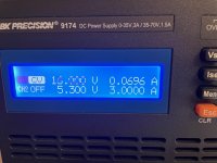
I tested the board and the squarer today. Worked fine with Vcc between 15 and 18 volt. Below that the sine is somewhat distorted.
Still I wonder if it is possible to have the Fifopi logic do the squaring? Was this already answered or discussed? I might have missed it.
As the squarer did not come with the sma connector, I can do sound test next week. I had to order them first at Digi-Key 😱
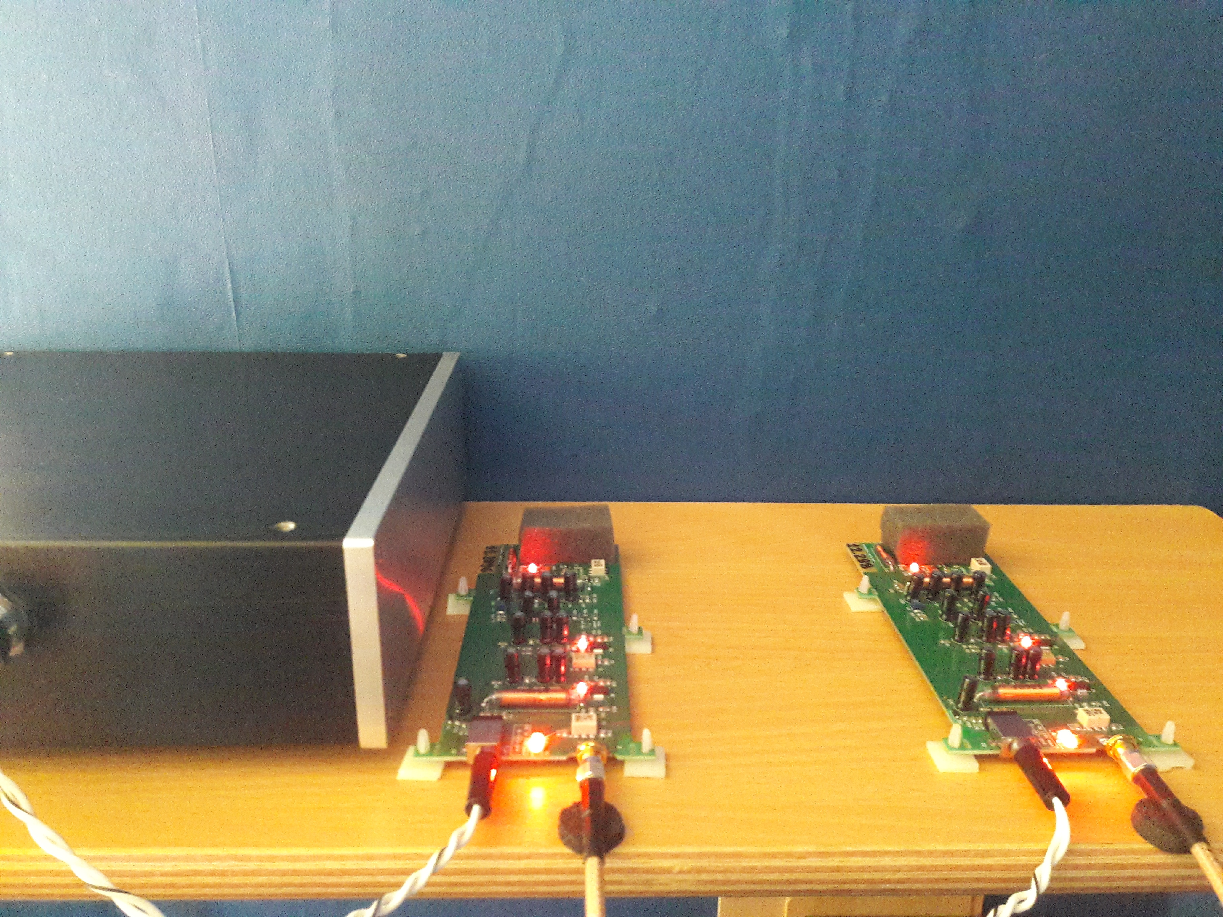
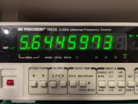
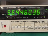
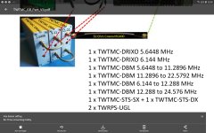
Below picture shows power consumption and the clock frequency at cold start and warm up situation
Still I wonder if it is possible to have the Fifopi logic do the squaring? Was this already answered or discussed? I might have missed it.
As the squarer did not come with the sma connector, I can do sound test next week. I had to order them first at Digi-Key 😱
Below picture shows power consumption and the clock frequency at cold start and warm up situation
Attachments
Hello,
If you would compare the clock plus board to a cartridge tonearm combo mounted on a sub chassis turntable and you would make a nice circle (aerial ) of the garden hose phono cable and lay it flat on the furniture next to the turntable what would be the benefit of the subchassis?
Because the circuit just uses a tiny current no need to use a thick cable there. Maybe just two pieces of magnet wire. JUST enough "" coating " to keep it isolated from air.Twisted it will be more rigid.
I found some rectangular aluminium in my stock that i could mount next to each other on one panel and on the front side i could give each rectangle it own front plate .
I remember from the past about making enclosure which are to " sturdy/ thick " sand will just add weight but no vibration killing properties. Make the metal kind of thin so it will have tendency to vibrate and then before it actually does stop it with sand.
SO probably not use anything to interconnect the 6 rectangles . Only the cables.
Make a thin aluminium? Box pour in some dry sand position the 6 rectangles on the sand and pour in the rest of the sand so the rectangles are kind of drowning.
You could rest the box on ........ or let it swing? If you will give it a little push would you hear that? I dont think so. Will an airborne vibration travel trough the outside box, through a few centimeter sand, than through the rectangular, than a little air and than through a cork to knock on the clock covered with a little felt?
Greetings,Eduard
Attachments
I changed out the soldered pigtail and used SMA terminated coax end to end. You and eduard were absolutely correct. There is a clear improvement in sound. Thank you both for pressing me on this.from an impedance integrity point of view, a connection like that is a carnage 🙂
great efforts was done in order to keep the impedance controlled all over the board... it's a pity to mess it up right at the output.
then... if you hear a difference, i don't know...
I've ordered RG400 cables of the proper length for my final set up.
The sound of this thing after 5 days (and proper coax) is to die for!
... is to die for!
can't quote more

... i felt a big improvement over my prev (surely not top-of-the-line nor state-of-the-art) NDK-SZs.
I am using a 22.xxx/24.xxx mhz to supply a full DSD chain...
Despite the fact that Sigma-delta-demulators should be fairly insensible to phasenoise, i felt a great benefit using thoose oscillators.
Last edited:
Indeed wlowes, good work, but as others have mentioned, the soldered coax rigid cable is currently undoing all the good work. It may not seem logical to worry, in fact it may seem counterproductive, but the impedance is under attack from such an arrangement. Having the wrong trace width and proportion to ground, thickness of the pcb is enough to cause a mismatch. Crimped/cold welded SMA is preferred; resist the urge to solder.
Agreed. It was tempting to try to use a soldered cable while waiting for new cables to come in. But having now replaced with properly terminated cable it is confirmed by listening that the solder connection was causing a problem. It was very good, now great.
While focusing on the problem with a soldered pigtail, I remembered that any sharp angle in the signal path is a potential problem. It occurred that when I soldered the light gauge wire to the leads of the crystal that I did it at a right angle. So I changed that as well so that the lead wire was soldered parallel to the crystal lead and making a nice gentle arc to the PCB. I don't know if that was in any way useful as I made the two changes without listening after each one. I only mention it in case it also had an impact. All I do know is changing these two sharp angle solder joints did improve the sound.
While focusing on the problem with a soldered pigtail, I remembered that any sharp angle in the signal path is a potential problem. It occurred that when I soldered the light gauge wire to the leads of the crystal that I did it at a right angle. So I changed that as well so that the lead wire was soldered parallel to the crystal lead and making a nice gentle arc to the PCB. I don't know if that was in any way useful as I made the two changes without listening after each one. I only mention it in case it also had an impact. All I do know is changing these two sharp angle solder joints did improve the sound.
Hello,
I remember that some analogue tuners had a normal piece of wire between the input circuitboard and the 75 ohm coaxial input chassis part. Back then we were told to replace the normal wire by a 75 ohm coaxial cable.
Probably here things are much more sensitive. Spending 1000 $ on creating a state of the art clock circuit and throwing out 90 % of the benefit by using the wrong way to connect a single connection.
Greetings,Eduard
> I remembered that any sharp angle in the signal path is a potential problem.
Then we have a lot of potential problems in our circuits....
Then we have a lot of potential problems in our circuits....
I'd say it was more like 10%, but we work hard for every 1% and I'm glad you pointed out the opportunity to improve. Thanks again!
> I remembered that any sharp angle in the signal path is a potential problem.
Then we have a lot of potential problems in our circuits....
higher the frequency, higher the chance that a "point" became an opportunity for emit radiations (antenna).
with the frequencies we are playing, shouldn't be much of a concern. but, as everyone says... everything count (maybe ?)
Last edited:
Makes sense. At 5.8gHz and 2.4g we worried about kinking a cable. I can imagine 5M is a different ball game.
sure !
be aware that every cable designed for carrying rf has a maximum (minimum) bending radius.
usually, and i want to stress the word - usually -, when you go past that point, you alter the mechanical proprieties of the dielectric, and, connected to that you alter the characteristic impedance.
You can pick the BEST-OF-THE-BEST cable, but if you fail to properly terminate ti (crimping, cold soldering is always to be preferred IMHO), or is managed poorly (crushed bends, smashed insulation...) you have lost all the benefits associated with it (or better, a big part of them).
an RG58 is a very fine cable for what we are doing, and should be more than adequate to do whats needed, but, just because we can, an RG400 is a sure improvement.
I'm positive that Andrea have already done many -specific- tests on each and every commond rf cable in our use case scenario... so he can surely report, for the application in use, what is best.
Hello,
I once heard that if you create a routing for a cable resembling a loop it will start working as an antenna much easier than giving it straight corners.
But here it is other frequencies but there must be some guidelines for sure!
No matter how small the degrading if we can avoid it with a single page with do's and don't for 5$ it will be worth it.
Greetings,Eduard
As vibrations seems to be concerning...

i am doing a suspended rig (with elastic band) that should isolate fairly good.
If that fails to isolate... oh well, at least i'll enjoy the view 🙂
a nylon elastic cord will be zig-zagged between pins in the channels.
If i don't get tired CAMming, surely i will share how it will look like once finished.
- Status
- Not open for further replies.
- Home
- Source & Line
- Digital Line Level
- The Well Tempered Master Clock - Building a low phase noise/jitter crystal oscillator