Andrea!
I have still not built my old clocks...
I now wonder as the new stuff is getting finished, can I reuse the old crystals in any meaningful way and get some of the new boards? Or shall I build the old ones as they where intended? Or just get the new stuff?
My order at the time was:
22.5792 MHz Laptech crystal fundamental 1
24.5760 MHz Laptech crystal fundamental 1
TWTMC-C Xo PCB 2
TWTMC-D&D Daughter board PCB 1
TWTMC-DIL DIL adapter 4
If I still want 2 clocks; 22 and 24, what is your recommendation that I do?
If I take these and compare to the new stuff - how many dbc/hz better are the best new one compared, at say 1 Hz.
//
Hi TNT,
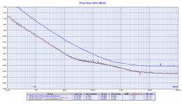
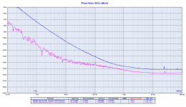
we have not measured the old Colpitts-Clapp oscillator with fundamental AT-Cut crystals at 22/24 MHz (no boards available), but since it's mainly the crystal to make the difference you can refer to the new Pierce TWTMC-PXO with 22/24 MHz crystals.
As you can see from the attached plots the differences are huge.
22.5792 MHz
- 30 dBc at 0.1 Hz
- 25 dBc at 1 Hz
- 25 dBc at 10 Hz
- 13 dBc noise floor
24.576 MHz
- 10 dBc at 0.1Hz
- 11 dBc at 1 Hz
- 14 dBc at 10 Hz
- 11 dBc noise floor
22.5792 MHz doublers
- 36 dBc at 0.1 Hz
- 37 dBc at 1 Hz
- 30 dBc at 10 Hz
- 6 dBc noise floor
Then the best 22/24 MHz performers are the DRIXO and EXO base oscillators at 5/6 MHz followed by two frequency doublers.
The cheaper option, although with state of the art performance, is the DRIXO and the EXO at 22/24 MHz (you save 4 frequency doublers and the crystals are less expensive).
Attachments

Andrea, Raj1, mars2, Sligolad
I added a TWTMC-SWITCH in the new google spreadsheet and wrote 1 board for myself, 1 for Raj1, 1 for mars2 and 2 for Sligolad.
TWTMC_Summary of Orders - Google Sheets
Please check that I got it right and edit it if I got something wrong.
I cannot see your new line, is it still there ?
I cannot see your new line, is it still there ?
Yes, name is now TWTMC-SFDO
its in the end of the finished boards section (I don't know if it will be finished or semi-finished, but I put it there)
Could we also put a 24 / 25Mhz quartz on the list? The Aio board is too big for my needs, so I would rather use one of the old pierce boards without the doubler.
BTW, did you consider using the SC-cut/ Old Driscoll design ?
Seems the price difference with the sc cut crystal is only about 13 euro, and the sc would give lower phase noise? Old driscoll board looks small too..
I guess in the end we who have interest in 24 and/or 25 would have to syncronize in the same alternative to meet the crystal MOQ.
@Andrea: Hi Andrea - one question that I hope you may have time/be able to help with ...
Since I don't ever remember having had the need to play back neither an 88.2k nor a 176.4 kHz audio file I am considering simplifying the clock setup a bit. This will save a bit of complexity and cost.
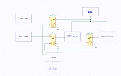
And also since I would prefer relays in the clock path I am thinking about something like the attached overview schematic. However, before deciding on this solution I would just like to ask you if you foresee any issues here (maybe feed through the relays to the doublers)? The squarer has been omitted from the drawing.
Relays could be the Panasonic DS latching relays that you at some earlier point in time have suggested (or something better?)
An alternative could be to use e.g. 74ac541 buffers in place of the relays. Looking at the LTC6957's phase noise plots I suspect it will add phase noise at the close-in frequencies ... (?)
Is the squarer really needed?
This question has been lurking in the back of my mind for a couple of hours now and I was wondering if anyone has made some measurements (in whichever possible way??) on the difference between using an external squarer as opposed to using the actual IC's - DAC or ADC - internal squaring functionality? I am aware of the curve slope vs. phase noise relation - the steeper the better - but wouldn't the DAC/ADC's own clock circuitry be able to perform the squaring as well as an external squarer? It would simplify things a bit but I haven't really seen this discussed anywhere - as if the basic assumption is that the DAC/ADC's own squaring circuitry is no good per se ..
Cheers & have a good day 😉
Jesper
Since I don't ever remember having had the need to play back neither an 88.2k nor a 176.4 kHz audio file I am considering simplifying the clock setup a bit. This will save a bit of complexity and cost.
And also since I would prefer relays in the clock path I am thinking about something like the attached overview schematic. However, before deciding on this solution I would just like to ask you if you foresee any issues here (maybe feed through the relays to the doublers)? The squarer has been omitted from the drawing.
Relays could be the Panasonic DS latching relays that you at some earlier point in time have suggested (or something better?)
An alternative could be to use e.g. 74ac541 buffers in place of the relays. Looking at the LTC6957's phase noise plots I suspect it will add phase noise at the close-in frequencies ... (?)
Is the squarer really needed?
This question has been lurking in the back of my mind for a couple of hours now and I was wondering if anyone has made some measurements (in whichever possible way??) on the difference between using an external squarer as opposed to using the actual IC's - DAC or ADC - internal squaring functionality? I am aware of the curve slope vs. phase noise relation - the steeper the better - but wouldn't the DAC/ADC's own clock circuitry be able to perform the squaring as well as an external squarer? It would simplify things a bit but I haven't really seen this discussed anywhere - as if the basic assumption is that the DAC/ADC's own squaring circuitry is no good per se ..
Cheers & have a good day 😉
Jesper
Attachments
there is a lot of ripped SACD out there with super quality. those are 88 and 176 family.... I have a a lot of them
...there is a lot of ripped SACD out there with super quality. those are 88 and 176 family.... I have a a lot of them
Yes, obviously, I didn't think about that as I haven't yet been playing DSD - but it should be an option - thanks Doede ;-)
Jesper
@Andrea: Hi Andrea - one question that I hope you may have time/be able to help with ...
Since I don't ever remember having had the need to play back neither an 88.2k nor a 176.4 kHz audio file I am considering simplifying the clock setup a bit. This will save a bit of complexity and cost.
And also since I would prefer relays in the clock path I am thinking about something like the attached overview schematic. However, before deciding on this solution I would just like to ask you if you foresee any issues here (maybe feed through the relays to the doublers)? The squarer has been omitted from the drawing.
Relays could be the Panasonic DS latching relays that you at some earlier point in time have suggested (or something better?)
An alternative could be to use e.g. 74ac541 buffers in place of the relays. Looking at the LTC6957's phase noise plots I suspect it will add phase noise at the close-in frequencies ... (?)
Is the squarer really needed?
This question has been lurking in the back of my mind for a couple of hours now and I was wondering if anyone has made some measurements (in whichever possible way??) on the difference between using an external squarer as opposed to using the actual IC's - DAC or ADC - internal squaring functionality? I am aware of the curve slope vs. phase noise relation - the steeper the better - but wouldn't the DAC/ADC's own clock circuitry be able to perform the squaring as well as an external squarer? It would simplify things a bit but I haven't really seen this discussed anywhere - as if the basic assumption is that the DAC/ADC's own squaring circuitry is no good per se ..
Cheers & have a good day 😉
Jesper
The TWTMC-STS-FSDO I'm designing is similar to your schematic.
I also use dual coil latching relays, multiplexers are cheaper but they add phase noise.
The Panasonic I suggested is fine, but there are even cheaper devices without any degradation.
Any digital input acts as a squarer because it works as on/off switch.
The problem is that not all digital inputs perform the same.
I have never feeding a DAC clock with sine wave but I suspect they are not designed to work in this way.
They are designed to work with high speed rising and falling edges.
As far as I know the AC and the ACT families have the best phase noise perfomance when used as a sine to square converter.
You can also use ECL logic but the performance is almost the same and the circuit become much more complex.
In our top DAC project we are testing several solutions to square the signals including a totally discrete circuit that's very large and complex.
Finally I will let you know the winner.
...
Yes, obviously, I didn't think about that as I haven't yet been playing DSD - but it should be an option - thanks Doede ;-)
Jesper
To give you an idea Jesper, I have roughly 5500x 88kHz and 7500x 176kHz tracks....
Yes, name is now TWTMC-SFDO
its in the end of the finished boards section (I don't know if it will be finished or semi-finished, but I put it there)
Thank you Thom, it is in there indeed !
The new Driscoll board is sine wave output so if you would a dual sine wave output you need a power splitter.
Conversely if you need square wave output I'm designing a dedicated board for the purpose, the TWTMC-STS-FSDO The Well Tempered Master Clock - Building a low phase noise/jitter crystal oscillator
Conversely if you need square wave output I'm designing a dedicated board for the purpose, the TWTMC-STS-FSDO The Well Tempered Master Clock - Building a low phase noise/jitter crystal oscillator
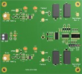
TWTMC-STS-FSDO
The layout of the fanout/switch board TWTMC-STS-FSDO is ready, I'm going to order the PCB proto.
I'm not sure there will be a semi-finished board since the LTC6957 is in MSOP-12 package very hard to solder.
The layout of the fanout/switch board TWTMC-STS-FSDO is ready, I'm going to order the PCB proto.
I'm not sure there will be a semi-finished board since the LTC6957 is in MSOP-12 package very hard to solder.
Attachments

Is possible leaving (does not implant) the whole switching logic, and use it as "sine_to_2x square" device?
Yes, I can provide 2 options:
- TWTMC-STS-FSDO-F, fanout version without switching logic
- TWTMC-STS-FSDO-S, switched output with switching logic
- TWTMC-STS-FSDO-F, fanout version without switching logic
- TWTMC-STS-FSDO-S, switched output with switching logic
The Buffalo BS-GS2016 switch preferred a LVCMOS output and need a 25MHz crystal and if I choose AT 6.25MHz, a TWTMC-PXO-AIO, I also need a TWTMC-STS to convert sine to square= LVCMOS output...Correctly?
If Yes, which TWTMC-STS SX or DX, do I have to order?
If Yes, which TWTMC-STS SX or DX, do I have to order?
- Status
- Not open for further replies.
- Home
- Source & Line
- Digital Line Level
- The Well Tempered Master Clock - Building a low phase noise/jitter crystal oscillator