Andrea, Raj1, mars2, Sligolad
I added a TWTMC-SWITCH in the new google spreadsheet and wrote 1 board for myself, 1 for Raj1, 1 for mars2 and 2 for Sligolad.
TWTMC_Summary of Orders - Google Sheets
Please check that I got it right and edit it if I got something wrong.
I added a TWTMC-SWITCH in the new google spreadsheet and wrote 1 board for myself, 1 for Raj1, 1 for mars2 and 2 for Sligolad.
TWTMC_Summary of Orders - Google Sheets
Please check that I got it right and edit it if I got something wrong.
Thank you to add the board, I have just update the code item in TWTMC-SFDO (Dual sine to square converter, switched/fanout, double output).
This is another thing.
If you would get the best form the 5/6 MHz oscillators I suggest to wait for the new discrete DAC Lite.
The board I was talking about would be designed with the following features:
- Input: 2 sine wave oscillators, one for each sample rate families)
- sine to square converters (LTC6957)
- double output (fanout, 2 output for each sample rate families to distribute the clock)
- or swithed output, single sample rate family at a time with parallel output (fanout to distribute the clock)
Double output and switched output would be alternatives to each other.
Switched output would require external control with the following options:
1) fixed High/Low control (Hiigh x48, Low x44.1)
2) 2 x fixed enable controls (high enabled, low disabled)
) 2 x pulsed enable controls, 30 ms min. (one for x48 + one for x44.1)
Please, let me know if there is enough interest on the above board (at least 10 pcs to start the design and the production).
I apologize but not sure if I understand the usage of the new TWTMC-SFDO board. It can be connected to 2 sine wave clocks then get squared and each "converted" to double output.
Finally, there are two options for the board. Double would mean 2+2 outputs, both families? and switched just 2 outputs of a single family??
Is this kind of description correct?😕 If this is the case I am interested as well.
I have just one wish I think it could be used by other people. It would be great if the squarer could be enabled/disabled in each family. In that case, it would be possible to use/play with other clocks already squared like pulsar, neutron and so on...
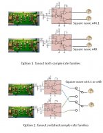
Good. Thank you for the diagram!
Andrea, would it be possible to bypass the squarer? Or to enable/disable it? 😱
Andrea, would it be possible to bypass the squarer? Or to enable/disable it? 😱
There is no need to bypass the LTC6957, it accepts almost all:
"The input can be a sine wave signal or a CML, LVPECL, TTL or CMOS logic signal."
I can provide both input interfaces, sine wave via SMA and CMOS via u.fl.
"The input can be a sine wave signal or a CML, LVPECL, TTL or CMOS logic signal."
I can provide both input interfaces, sine wave via SMA and CMOS via u.fl.
Andrea, Raj1, mars2, Sligolad
I added a TWTMC-SWITCH in the new google spreadsheet and wrote 1 board for myself, 1 for Raj1, 1 for mars2 and 2 for Sligolad.
TWTMC_Summary of Orders - Google Sheets
Please check that I got it right and edit it if I got something wrong.
Me too, 2 boards...
sounds great,
is it also possible using TWTMC-FSDO to switch between 44.1 and 176,4 (in fact bypassing the doublers?) using one 5,6 Mhz board and two doubelers to reach 22,579 Mhz for one STS- SX using the FifoPi?
is it also possible using TWTMC-FSDO to switch between 44.1 and 176,4 (in fact bypassing the doublers?) using one 5,6 Mhz board and two doubelers to reach 22,579 Mhz for one STS- SX using the FifoPi?
The board has 2 input so if you connect the first to a 5 MHz and the second to 22 MHz, then you connect the output to one of the clock input of the FifoPi, you can switch between 44.1 and 176.4kHz.
But if you are planning to use the same base 5MHz oscillator to feed both the TWTMC-FSDO and a couple of frequency doublers you need a Power Splitter like the onw I have suggested from Mini-Circuits
Permission denied...
But if you are planning to use the same base 5MHz oscillator to feed both the TWTMC-FSDO and a couple of frequency doublers you need a Power Splitter like the onw I have suggested from Mini-Circuits
Permission denied...
Andrea,
Is possible make this board with selectable 50R or 100R input?
For example serial connected 50R resistors, one of them shunted with 0R. If this shunt removed, the input load is 100R.
Paralleling two 100R inputs make four square output.
Is possible make this board with selectable 50R or 100R input?
For example serial connected 50R resistors, one of them shunted with 0R. If this shunt removed, the input load is 100R.
Paralleling two 100R inputs make four square output.
As I said I will provide both sine wave and CMOS inputs but I have to make the inputs compliant to the LT6957 specs (max +10dBm, better if less).
So each input has its own attenuator and impedance adapter to get them compliants to standard sine wave oscillators output and to standard 3V3 CMOS output.
So each input has its own attenuator and impedance adapter to get them compliants to standard sine wave oscillators output and to standard 3V3 CMOS output.
Could we also put a 24 / 25Mhz quartz on the list? The Aio board is too big for my needs, so I would rather use one of the old pierce boards without the doubler.
No problem, you can add the 24/25 MHz AT-Cut crystals to the list.
Again the issue could be the MOQ, 10 pcs for each frequency.
Again the issue could be the MOQ, 10 pcs for each frequency.
- Status
- Not open for further replies.
- Home
- Source & Line
- Digital Line Level
- The Well Tempered Master Clock - Building a low phase noise/jitter crystal oscillator