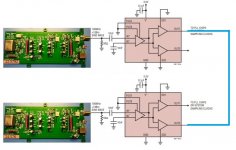
I will also probably need enabling/disabling functionality in my application. First I thought to implement this by using the enable signal to switch a relay and simply cut off the output. But now I'm thinking to maybe use the LTC6957 buffer. If I read the datasheet right, you could feed it sine wave and use it as squarer, and also do distribution into 2 signals, and finally it has enable functionality for both square outputs. I'm no clock expert so if I overlook something here then tell me...
Yes, you can use a pair of LTC6957, connect their ouptut and then you can use SD1/SD2 of both to enable/disable the oscillators.
Attachments
So you could just help me and the community explaining how to distribute the clock.
I'm very busy (I also have a job and a life) so I would appreciate very much your help.
All input data is not at hand so I'm afraid not. Complete and clear documentation minimise support hours.
Then again I don't think I could really as I did not work with HW design.
I wish I could be of more help- sorry.
//
Yes, thanks Andrea.
And another advantage, the 6957 needs only minimum 0.2V p-p on the input, so perhaps in this case it would be possible to use 3 doublers? (I will not need it however).
And another advantage, the 6957 needs only minimum 0.2V p-p on the input, so perhaps in this case it would be possible to use 3 doublers? (I will not need it however).
All input data is not at hand so I'm afraid not. Complete and clear documentation minimise support hours.
Then again I don't think I could really as I did not work with HW design.
I wish I could be of more help- sorry.
//
I meant only the basic rules to distribute the clock (sine or square wave) regardless of my oscillators and final applications.
Anyway thanks.
Yes, thanks Andrea.
And another advantage, the 6957 needs only minimum 0.2V p-p on the input, so perhaps in this case it would be possible to use 3 doublers? (I will not need it however).
I believe so but should be tested.
Hi Andrea,
For the DRIXO oscillators, I see there is a single DC input specified for 18VDC max. Can some of the onboard regulators be bypassed so that critical areas can be fed directly from 3.3V LIPO cells?
-Raja
For the DRIXO oscillators, I see there is a single DC input specified for 18VDC max. Can some of the onboard regulators be bypassed so that critical areas can be fed directly from 3.3V LIPO cells?
-Raja
Originally Posted by andrea_mori
Sorry, but I don't understand what you have to connect after the squarer, can you elaborate?
I didn`t get detailed:
Assumed, that I could shut down one oscillator (maybe the specific squarer), would it be possible to simply (after impedance matching series resitors, like in the schematic, that I`ve posted) tie both squarer outputs together?
Last edited:
Hi Andrea,
For the DRIXO oscillators, I see there is a single DC input specified for 18VDC max. Can some of the onboard regulators be bypassed so that critical areas can be fed directly from 3.3V LIPO cells?
-Raja
In the guide is specified:
Power supply: 12-18 Vdc 60 mA
There are no regulators on board.
Of course you can power it by LiFePo4 batteries (we are doing so) but you don't need 3V3, you need 12 to 12 Vdc (suggested 16V5, 5 batteries in series).
I didn`t get detailed:
Assumed, that I could shut down one oscillator (maybe the specific squarer), would it be possible to simply (after impedance matching series resitors, like in the schematic, that I`ve posted) tie both squarer outputs together?
You cannot tie both square outputs together, you get a short circuit.
The squarers do not provide the enable pin, therefore even if you shut down one of them the other sees the output of the first one that's not a high impedance level.
The Crystek you are referring has the enable pin, so it move to high impedance when is disabled.
In a few words it's not possible.
Thanks, Andrea. I didn't realize the low-level circuitry operates at those voltages.
All the circuit operates at those voltages, oscillator and buffers, 12V is the minumum voltage required but I suggest 16-17 Vdc for a better noise floor.
Originally Posted by andrea_mori
...In a few words it's not possible.
Thanks for the clarification.
All the circuit operates at those voltages, oscillator and buffers, 12V is the minumum voltage required but I suggest 16-17 Vdc for a better noise floor.
Got it. Thank you!
Dear Andrea,
Regarding SMA coaxial cables, what's the good length between the two Hamond boxes (oscillator to doubler and doubler to doubler) ?
Thanks
Regarding SMA coaxial cables, what's the good length between the two Hamond boxes (oscillator to doubler and doubler to doubler) ?
Thanks
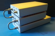
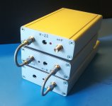
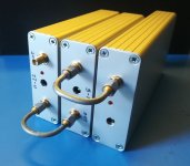
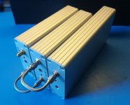
As short as possible like in the following pictures.
Attachments

WARNING!
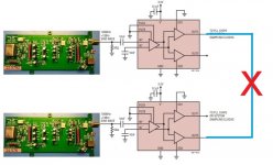
I does not work as a multiplexer between the two clocks because the output of the LTC6957 can not be put in a high impedance (3-state) condition.
You can only use the LTC6957 as fanout buffer to get 2 square wave outputs from a single sine wave oscillator.
If there will be enough interest I could design a dedicated board to switch between 2 clocks with enable inputs.
Please, let me know.
Yes, you can use a pair of LTC6957, connect their ouptut and then you can use SD1/SD2 of both to enable/disable the oscillators.
I does not work as a multiplexer between the two clocks because the output of the LTC6957 can not be put in a high impedance (3-state) condition.
You can only use the LTC6957 as fanout buffer to get 2 square wave outputs from a single sine wave oscillator.
If there will be enough interest I could design a dedicated board to switch between 2 clocks with enable inputs.
Please, let me know.
Attachments
- Status
- Not open for further replies.
- Home
- Source & Line
- Digital Line Level
- The Well Tempered Master Clock - Building a low phase noise/jitter crystal oscillator