The other user of the Ian FIFO
For use the XO and daughter board with Fifo of Ian how to complete the form assembly,apart connection between board, they are the options to take?
I would like to see a reference too before I finalize my order.
Hi mcluxun ,i have send a P.M to Ian to help choose option.
But Ian is certainly busy by the feasts.
But Ian is certainly busy by the feasts.
Tips for Ian's builders.
If you want to use daughter board, D&D, with Ian's Dual XO board, there's no need to select switching logic.
But, dividers and delayed are required.
I beg Andrea to confirm this statement.
Regards
Phil
If you want to use daughter board, D&D, with Ian's Dual XO board, there's no need to select switching logic.
But, dividers and delayed are required.
I beg Andrea to confirm this statement.
Regards
Phil
Tips for Ian's builders.
If you want to use daughter board, D&D, with Ian's Dual XO board, there's no need to select switching logic.
But, dividers and delayed are required.
I beg Andrea to confirm this statement.
Regards
Phil
The ideal would a mounting form "type" for use with the Ian Dual XO board,it's possible Korben?
Last edited:
Connecting with Ian's boards
All the users who want to use TWTMC boards with Ian's Fifo buffer:
as you probably know I did ask Ian to understand the right way to do the job on his thread
http://www.diyaudio.com/forums/digi...project-ultimate-weapon-fight-jitter-346.html
I'm waiting for Ian to confirm what I wrote.
BTW, I think you have to use one of the following:
Dual XO, FIFO buffer
1st option: the two TWTMC-C (J1/J2) have to be connected to Ian's Dual XO clock board via u.fl. cables, using Ian's XO adapters. Output will be taken from Ian's Dual XO clock board. TWTMC-D&D has to be used for power supply only.
2nd option: using Ian's Dual XO clock board for automatic fs detector only (one of the two OE pin of the XO sockets of Ian's Dual XO clock). Two TWTMC-C have to be soldered with TWTMC-D&D; master clock via u.fl. cable from TWTMC-D&D (J13/J14) to Ian's FIFO board J6. Output taken from Ian's FIFO board, without any reclocking. TWTMC-D&D will be used both for power supply and switching logic (RF relay)
3rd option: no Ian's Dual XO clock board. The same as above, manually switching between the two XO (unless the source provides automatic fs detector).
Using the first option, you need both Ian's Fifo and Ian's Dual XO clock.
You need two TWTMC-C XO (eg. 22.5792 MHz and 24.5760 MHz) and one TWTMC-D&D daughter board, that will be used to supply the two XO boards.
So, you have to select "Rectification and filtering" + "Regulators on board" only.
You cannot use Ian's Dual XO clock board to supply the two XO, since they need two rails, +15V and +3V3, while Ian's board provides 3V3 rail only.
The two XO will be soldered to the daughter board using the pin strips for the power supply only (XO-1 Vo and Vs pins, XO-2 Vo and Vs pins of the daughter board).
Seems Ian's XO adapter does not provide footprint for u.fl. connector, so you have to adapt it on the board, using clock and ground pads.
Then, you can use two u.fl. short cable to connect J1 or J2 from the two XO, to Ian's XO adapters.
As an alternative, you can use two u.fl. cables with single connector termination: u.fl. connectors will be plugged into the receptable of the XO boards, while the other terminations, connector less, have to be soldered to Ian's XO adapters (clock and ground).
Finally, I2S output will be taken from Ian's Dual XO clock board, that implements I2S reclocking.
Ian's Dual XO clock board performs the swithing between the two clocks.
Using the second option, you need again both Ian's Fifo and Ian's Dual XO clock, two TWTMC-C XO (eg. 22.5792 MHz and 24.5760 MHz) and one TWTMC-D&D daughter board.
With this option, you have also to select "Dual XO option" (K1 relay + logic), as the daughter board customization.
Again, you cannot use Ian's Dual XO clock board to supply the two XO.
The two XO will be soldered to the daughter board using all the pin strips: power supply (XO-1 Vo and Vs pins, XO-2 Vo and Vs pins of the daughter board) and clock output (Out pin of the daughter board).
Then you can use a single u.fl. cable, to connect the master clock from the daughter board (J13 or J14) to Ian's Fifo board (J6).
One of the two OE pins and ground pin of Ian's Dual XO clock board, using an XO adapter, have to be connected to the clock selection pins of the daughter board (L/H).
I2S output will be taken directly from Ian's FIfo board, without any reclocking.
TWTMC-D&D daughter board performs the swithing between the two clocks, via RF realy.
The third option could be used if you are planning to use Ian's Fifo board without Ian's Dual Xo clock board.
This implementation is the same as above, but no automatic fs detector is available.
So you can switch manually between the two XO, unless your source provides this feature. If yes, you have to connect your source to the input selection pins of the daughter board.
I hope this helps, but I also hope Ian let us know what is the better way.
As soon as I'll find a little free time, I'll try to publish some pictures (next days).
.... Using the first option, you need both Ian's Fifo and Ian's Dual XO clock.
You need two TWTMC-C XO (eg. 22.5792 MHz and 24.5760 MHz) and one TWTMC-D&D daughter board, that will be used to supply the two XO boards.
So, you have to select "Rectification and filtering" + "Regulators on board" only. ...
I suppose you don't have to select the "rect and filtering" but could feed the D&D the needed DC instead?
//
I suppose you don't have to select the "rect and filtering" but could feed the D&D the needed DC instead?
//
You could feed D&D daughter board with 17 Vac (J15 "Rectification and filtering" selected), or with 22-23 Vdc (J18 "Rectification and filtering" unselected).
Crystals and PCB Order Form
For those who are requesting crystals and PCB, please:
- download the attached spreadsheet
- rename it as your diyaudio alias _ TWTMC_OrderForm (for example andrea_mori_TWTMC_OrderForm.xls)
- fill all the requested data
- send it to my email address (see spreadsheet)
A few notes:
- pay attention to "Assembly service", indicate "Yes" if you are requesting the service, so I know I have to send crystal and PCB to Phil
- "Tracking option" (within EU), only if "Assembly service" is not requested
I will collect all the orders and I will add prices and total amount.
I'll send to each member the final spreadsheet with total amount.
I'll send to each member the payment request by PayPal, according to each spreadsheet.
Please, remember that at this moment we have reached the MOQ for these crystal frequency:
11.2896 MHz
22.5792 MHz
24.5760 MHz
45.1584 MHz
49.1520 MHz
so, don't add other frequencies in the order form, until every MOQ will be reached.
Attachments
- andrea_mori : 5 x 5.6448MHz + 2 x 11.2896MHz + 3 X 22.5792 MHz + 3 x 24.576 MHz + 1 x 45.1584 MHz + 1 x 49.152 MHz + 1 x 90.3168 MHz + 1 x 98.304 MHz + 10 x PCB + 4 x daughter board PCB
- Eldam : 1 x 5.6448MHz + 1 X 22.5792 MHz + 1 x 24.576 MH + 2 x daughter board PCB + 4 x PCB
- esgigt : 1 x 11.2896 Mhz + 1 x PCB, soldered if possible
- fralippo : 1 x 22.5792 MHz and 1 x 24.576 MHz + 2 x PCB + 1 x daughter board PCB
- mravinsky : 2 x 11.2896 Mhz + 2 x XO PCB + 1 x Daughter board PCB
- TNT : 1x22.5792MHz 1x24.5760MHz + 2 x PCB, + 1 x daughter board, all soldered if possible
- 1audio : 2x22.5792MHz 2x24.5760MHz + 2 x PCB + daughter board.
- randytsuch : 2x25.0000MHz + 4 x PCB + 1 x daughterboard
- myint67 : 1x11.2896mhz ,1x22.5792,1x45.1584,1x49.152 ,4 PCB ,2xdaughter board , soldered if possible
- kf_tam : 2x PCB
- BDL : 1 x 11.2896 MHz + 4 x PCB + 1 x daughter board PCB
- thorstenlarsen : 2 x 11.2896 MHz + 2 x PCB
- Zoran : 1x22.5792MHz 1x24.5760MHz + 2 x PCB, (soldered or not...) + 1 x 11.2896 MHz + 1 x PCB
- walangalam : 1 x 11.2896 Mhz + 2 x PCB
- AR2: 1 x 22.5792 MHz and 1 x 24.576 MHz + 2 x PCB (soldering not needed)
- mcluxun: 1 x 22.5792 MHz and 1 x 24.576 MHz + 2 x PCB + 1 x daughterboard (soldering if possible)
- damohpi: 1 x 11.2896 + 1x PCB unsoldered
- noizas : 2 x 5.6448MHz + 2 x 11.2896MHz + 4 x PCB
- badrisuper : : 1 x 11.2896 Mhz + 2 x PCB
- Clsidxxl: 1 x 45.1584 MHz + 1 x 49.152 MHz+daughter board + 2 x PCB -With Assembly Service
- zeta4 1x 22.5792Mhz + 1 x PCB (soldering not needed)
- chertk : 1 x 22.5792 MHz and 1 x 24.576 MHz + 2 x PCB + 1 x daughter board
- hirez69: 1 x 22.5792 MHz and 1 x 24.576 MHz + 1 x 45.1584 MHz + 1 x 49.152 MHz + 4 x PCB (soldered) + 1 x daughter board
- palmito : 1 x 45.1584 MHz + 1 x 49.152 MHz; 1 x 22.5792MHz 1 x 24.5760MHz; 2 PCBs; 2 daughter boards.
- gentlevoice: 1 x 22.5792MHz + 1 x 24.576 MHz + 1 x 45.1584 MHz + 1 x 49.152 MHz + 1*PCB
- naimster: 1x 22.5792 MHz + 1x 24.576 MHz + 2x PCB + 1x daughterboard (soldered if possible)
- zenelectro : 1 x 45.1584 MHz + 1 x 49.152 MHz + 2 x PCB's + 1 x daughterboard (soldered if possible)
- Ryssen : 1 x 24.576 MHz + 1 x PCB soldered
- flowerpot : 1 x 45.1584 MHz + 1 x 49.152 MHz + 2 x PCB + 1 x daughter board PCB
- deanoUK : 1 x 45.1584 MHz + 1 x 49.152 MHz + 2 x PCB + 1 x daughter board PCB
- Miklos: 1 x 11.2896MHz + 2 x PCB + 1 x 16.9344 MHz
- Kannan_s:1 x 45.1584 MHz + 1 x 49.152 MHz + 2 x PCB + 1 x daughter board PCB
- Acko : 1 x 45.1584 MHz + 1 x 49.152 MHz + 2 x PCB + 1 x daughter board PCB
- tuyen : 1 x 45.1584 MHz + 1 x 49.152 MHz + 2 x PCB's + 1 x daughterboard (soldered if possible)
- Malvin : 1 x 45.1584 MHz + 1 x 49.152 MHz + 2 x PCB + 1 x daughter board PCB
- Marlowe: 3 x 16.9344Mhz + 3 x 25MHz + 1 x 45.1584 MHz + 1 x 49.152 MHz + 1 x 22.5792 MHz + 1 x 24.576 MHz + 8 x PCB + 3 x daughter board PCB
- ppap64: 1 x 45.1584 MHz + 1 x 49.152 MHz + 2 x PCB + 1 x daughter board(soldered if possible)
- Superdad: 1 x 22.5792 MHz and 1 x 24.576 MHz + 2 x PCB + 1 x daughter board (soldered if possible)
- vita:1 x 24.576Mhz + 6 PCB
- bkdog 1 x 90.3168 MHz + 1 x 98.304 MHz + 2 x PCB + 2 x daughter board (soldered if poss)
Updated my order.
Can someone comment on the quality of this discrete clock oscillator in comparison to a CMOS Xtal oscillator as build into the AK4115 or similar chips?
Is the jitter of a CMOS build in oscillator good enough for the new 127 dB AKM ADC or do i need a discrete oscillator for best performance? Any thoughts or measurements?
Background is that i need a master clock for the "Digital Equalizer Arm-M4" project.
Is the jitter of a CMOS build in oscillator good enough for the new 127 dB AKM ADC or do i need a discrete oscillator for best performance? Any thoughts or measurements?
Background is that i need a master clock for the "Digital Equalizer Arm-M4" project.
- andrea_mori : 5 x 5.6448MHz + 2 x 11.2896MHz + 3 X 22.5792 MHz + 3 x 24.576 MHz + 1 x 45.1584 MHz + 1 x 49.152 MHz + 1 x 90.3168 MHz + 1 x 98.304 MHz + 10 x PCB + 4 x daughter board PCB
- Eldam : 1 x 5.6448MHz + 1 X 22.5792 MHz + 1 x 24.576 MH + 2 x daughter board PCB + 4 x PCB
- esgigt : 1 x 11.2896 Mhz + 1 x PCB, soldered if possible
- fralippo : 1 x 22.5792 MHz and 1 x 24.576 MHz + 2 x PCB + 1 x daughter board PCB
- mravinsky : 2 x 11.2896 Mhz + 2 x XO PCB + 1 x Daughter board PCB
- TNT : 1x22.5792MHz 1x24.5760MHz + 2 x PCB, + 1 x daughter board, all soldered if possible
- 1audio : 2x22.5792MHz 2x24.5760MHz + 2 x PCB + daughter board.
- randytsuch : 2x25.0000MHz + 4 x PCB + 1 x daughterboard
- myint67 : 1x11.2896mhz ,1x22.5792,1x45.1584,1x49.152 ,4 PCB ,2xdaughter board , soldered if possible
- kf_tam : 2x PCB
- BDL : 1 x 11.2896 MHz + 4 x PCB + 1 x daughter board PCB
- thorstenlarsen : 2 x 11.2896 MHz + 2 x PCB
- Zoran : 1x22.5792MHz 1x24.5760MHz + 2 x PCB, (soldered or not...) + 1 x 11.2896 MHz + 1 x PCB
- walangalam : 1 x 11.2896 Mhz + 2 x PCB
- AR2: 1 x 22.5792 MHz and 1 x 24.576 MHz + 2 x PCB (soldering not needed)
- mcluxun: 1 x 22.5792 MHz and 1 x 24.576 MHz + 2 x PCB + 1 x daughterboard (soldering if possible)
- damohpi: 1 x 11.2896 + 1x PCB unsoldered
- noizas : 2 x 5.6448MHz + 2 x 11.2896MHz + 4 x PCB
- badrisuper : : 1 x 11.2896 Mhz + 2 x PCB
- Clsidxxl: 1 x 45.1584 MHz + 1 x 49.152 MHz+daughter board + 2 x PCB -With Assembly Service
- zeta4 1x 22.5792Mhz + 1 x PCB (soldering not needed)
- chertk : 1 x 22.5792 MHz and 1 x 24.576 MHz + 2 x PCB + 1 x daughter board
- hirez69: 1 x 22.5792 MHz and 1 x 24.576 MHz + 1 x 45.1584 MHz + 1 x 49.152 MHz + 4 x PCB (soldered) + 1 x daughter board
- palmito : 1 x 45.1584 MHz + 1 x 49.152 MHz; 1 x 22.5792MHz 1 x 24.5760MHz; 2 PCBs; 2 daughter boards.
- gentlevoice: 1 x 22.5792MHz + 1 x 24.576 MHz + 1 x 45.1584 MHz + 1 x 49.152 MHz + 1*PCB
- naimster: 1x 22.5792 MHz + 1x 24.576 MHz + 2x PCB + 1x daughterboard (soldered if possible)
- zenelectro : 1 x 45.1584 MHz + 1 x 49.152 MHz + 2 x PCB's + 1 x daughterboard (soldered if possible)
- Ryssen : 1 x 24.576 MHz + 1 x PCB soldered
- flowerpot : 1 x 45.1584 MHz + 1 x 49.152 MHz + 2 x PCB + 1 x daughter board PCB
- deanoUK : 1 x 45.1584 MHz + 1 x 49.152 MHz + 2 x PCB + 1 x daughter board PCB
- Miklos: 1 x 11.2896MHz + 2 x PCB + 1 x 16.9344 MHz
- Kannan_s:1 x 45.1584 MHz + 1 x 49.152 MHz + 2 x PCB + 1 x daughter board PCB
- Acko : 1 x 45.1584 MHz + 1 x 49.152 MHz + 2 x PCB + 1 x daughter board PCB
- tuyen : 1 x 45.1584 MHz + 1 x 49.152 MHz + 2 x PCB's + 1 x daughterboard (soldered if possible)
- Malvin : 1 x 45.1584 MHz + 1 x 49.152 MHz + 2 x PCB + 1 x daughter board PCB
- Marlowe: 3 x 16.9344Mhz + 3 x 25MHz + 1 x 45.1584 MHz + 1 x 49.152 MHz + 1 x 22.5792 MHz + 1 x 24.576 MHz + 8 x PCB + 3 x daughter board PCB
- ppap64: 1 x 45.1584 MHz + 1 x 49.152 MHz + 2 x PCB + 1 x daughter board(soldered if possible)
- Superdad: 1 x 22.5792 MHz and 1 x 24.576 MHz + 2 x PCB + 1 x daughter board (soldered if possible)
- vita:1 x 24.576Mhz + 6 PCB
- bkdog 1 x 90.3168 MHz + 1 x 98.304 MHz + 2 x PCB + 2 x daughter board (soldered if poss)
Updated my order.
Please update for list for 1 crystal, 11.2896mhz
Thanks
Congrats on the project Andrea! Looks fantastic.
- andrea_mori : 5 x 5.6448MHz + 2 x 11.2896MHz + 3 X 22.5792 MHz + 3 x 24.576 MHz + 1 x 45.1584 MHz + 1 x 49.152 MHz + 1 x 90.3168 MHz + 1 x 98.304 MHz + 10 x PCB + 4 x daughter board PCB
- Eldam : 1 x 5.6448MHz + 1 X 22.5792 MHz + 1 x 24.576 MH + 2 x daughter board PCB + 4 x PCB
- esgigt : 1 x 11.2896 Mhz + 1 x PCB, soldered if possible
- fralippo : 1 x 22.5792 MHz and 1 x 24.576 MHz + 2 x PCB + 1 x daughter board PCB
- mravinsky : 2 x 11.2896 Mhz + 2 x XO PCB + 1 x Daughter board PCB
- TNT : 1x22.5792MHz 1x24.5760MHz + 2 x PCB, + 1 x daughter board, all soldered if possible
- 1audio : 2x22.5792MHz 2x24.5760MHz + 2 x PCB + daughter board.
- randytsuch : 2x25.0000MHz + 4 x PCB + 1 x daughterboard
- myint67 : 1x11.2896mhz ,1x22.5792,1x45.1584,1x49.152 ,4 PCB ,2xdaughter board , soldered if possible
- kf_tam : 2x PCB
- BDL : 1 x 11.2896 MHz + 4 x PCB + 1 x daughter board PCB
- thorstenlarsen : 2 x 11.2896 MHz + 2 x PCB
- Zoran : 1x22.5792MHz 1x24.5760MHz + 2 x PCB, (soldered or not...) + 1 x 11.2896 MHz + 1 x PCB
- walangalam : 1 x 11.2896 Mhz + 2 x PCB
- AR2: 1 x 22.5792 MHz and 1 x 24.576 MHz + 2 x PCB (soldering not needed)
- mcluxun: 1 x 22.5792 MHz and 1 x 24.576 MHz + 2 x PCB + 1 x daughterboard (soldering if possible)
- damohpi: 1 x 11.2896 + 1x PCB unsoldered
- noizas : 2 x 5.6448MHz + 2 x 11.2896MHz + 4 x PCB
- badrisuper : : 1 x 11.2896 Mhz + 2 x PCB
- Clsidxxl: 1 x 45.1584 MHz + 1 x 49.152 MHz+daughter board + 2 x PCB -With Assembly Service
- zeta4 1x 22.5792Mhz + 1 x PCB (soldering not needed)
- chertk : 1 x 22.5792 MHz and 1 x 24.576 MHz + 2 x PCB + 1 x daughter board
- hirez69: 1 x 22.5792 MHz and 1 x 24.576 MHz + 1 x 45.1584 MHz + 1 x 49.152 MHz + 4 x PCB (soldered) + 1 x daughter board
- palmito : 1 x 45.1584 MHz + 1 x 49.152 MHz; 1 x 22.5792MHz 1 x 24.5760MHz; 2 PCBs; 2 daughter boards.
- gentlevoice: 1 x 22.5792MHz + 1 x 24.576 MHz + 1 x 45.1584 MHz + 1 x 49.152 MHz + 1*PCB
- naimster: 1x 22.5792 MHz + 1x 24.576 MHz + 2x PCB + 1x daughterboard (soldered if possible)
- zenelectro : 1 x 45.1584 MHz + 1 x 49.152 MHz + 2 x PCB's + 1 x daughterboard (soldered if possible)
- Ryssen : 1 x 24.576 MHz + 1 x PCB soldered
- flowerpot : 1 x 45.1584 MHz + 1 x 49.152 MHz + 2 x PCB + 1 x daughter board PCB
- deanoUK : 1 x 45.1584 MHz + 1 x 49.152 MHz + 2 x PCB + 1 x daughter board PCB
- Miklos: 1 x 11.2896MHz + 2 x PCB + 1 x 16.9344 MHz
- Kannan_s:1 x 45.1584 MHz + 1 x 49.152 MHz + 2 x PCB + 1 x daughter board PCB
- Acko : 1 x 45.1584 MHz + 1 x 49.152 MHz + 2 x PCB + 1 x daughter board PCB
- tuyen : 1 x 45.1584 MHz + 1 x 49.152 MHz + 2 x PCB's + 1 x daughterboard (soldered if possible)
- Malvin : 1 x 45.1584 MHz + 1 x 49.152 MHz + 2 x PCB + 1 x daughter board PCB
- Marlowe: 3 x 16.9344Mhz + 3 x 25MHz + 1 x 45.1584 MHz + 1 x 49.152 MHz + 1 x 22.5792 MHz + 1 x 24.576 MHz + 8 x PCB + 3 x daughter board PCB
- ppap64: 1 x 45.1584 MHz + 1 x 49.152 MHz + 2 x PCB + 1 x daughter board(soldered if possible)
- Superdad: 1 x 22.5792 MHz and 1 x 24.576 MHz + 2 x PCB + 1 x daughter board (soldered if possible)
- vita:1 x 24.576Mhz + 6 PCB
- bkdog 1 x 90.3168 MHz + 1 x 98.304 MHz + 2 x PCB + 2 x daughter board (soldered if poss)
- ryanj 1 x 11.2896 Mhz + 1 PCB + 1 daughter PCB
Please update for list for 1 crystal, 11.2896mhz
Thanks
You can update yourself the list, copying the last one and adding your desired crystal/PCB.
Congrats on the project Andrea! Looks fantastic.
- andrea_mori : 5 x 5.6448MHz + 2 x 11.2896MHz + 3 X 22.5792 MHz + 3 x 24.576 MHz + 1 x 45.1584 MHz + 1 x 49.152 MHz + 1 x 90.3168 MHz + 1 x 98.304 MHz + 10 x PCB + 4 x daughter board PCB
- Eldam : 1 x 5.6448MHz + 1 X 22.5792 MHz + 1 x 24.576 MH + 2 x daughter board PCB + 4 x PCB
- esgigt : 1 x 11.2896 Mhz + 1 x PCB, soldered if possible
- fralippo : 1 x 22.5792 MHz and 1 x 24.576 MHz + 2 x PCB + 1 x daughter board PCB
- mravinsky : 2 x 11.2896 Mhz + 2 x XO PCB + 1 x Daughter board PCB
- TNT : 1x22.5792MHz 1x24.5760MHz + 2 x PCB, + 1 x daughter board, all soldered if possible
- 1audio : 2x22.5792MHz 2x24.5760MHz + 2 x PCB + daughter board.
- randytsuch : 2x25.0000MHz + 4 x PCB + 1 x daughterboard
- myint67 : 1x11.2896mhz ,1x22.5792,1x45.1584,1x49.152 ,4 PCB ,2xdaughter board , soldered if possible
- kf_tam : 2x PCB
- BDL : 1 x 11.2896 MHz + 4 x PCB + 1 x daughter board PCB
- thorstenlarsen : 2 x 11.2896 MHz + 2 x PCB
- Zoran : 1x22.5792MHz 1x24.5760MHz + 2 x PCB, (soldered or not...) + 1 x 11.2896 MHz + 1 x PCB
- walangalam : 1 x 11.2896 Mhz + 2 x PCB
- AR2: 1 x 22.5792 MHz and 1 x 24.576 MHz + 2 x PCB (soldering not needed)
- mcluxun: 1 x 22.5792 MHz and 1 x 24.576 MHz + 2 x PCB + 1 x daughterboard (soldering if possible)
- damohpi: 1 x 11.2896 + 1x PCB unsoldered
- noizas : 2 x 5.6448MHz + 2 x 11.2896MHz + 4 x PCB
- badrisuper : : 1 x 11.2896 Mhz + 2 x PCB
- Clsidxxl: 1 x 45.1584 MHz + 1 x 49.152 MHz+daughter board + 2 x PCB -With Assembly Service
- zeta4 1x 22.5792Mhz + 1 x PCB (soldering not needed)
- chertk : 1 x 22.5792 MHz and 1 x 24.576 MHz + 2 x PCB + 1 x daughter board
- hirez69: 1 x 22.5792 MHz and 1 x 24.576 MHz + 1 x 45.1584 MHz + 1 x 49.152 MHz + 4 x PCB (soldered) + 1 x daughter board
- palmito : 1 x 45.1584 MHz + 1 x 49.152 MHz; 1 x 22.5792MHz 1 x 24.5760MHz; 2 PCBs; 2 daughter boards.
- gentlevoice: 1 x 22.5792MHz + 1 x 24.576 MHz + 1 x 45.1584 MHz + 1 x 49.152 MHz + 1*PCB
- naimster: 1x 22.5792 MHz + 1x 24.576 MHz + 2x PCB + 1x daughterboard (soldered if possible)
- zenelectro : 1 x 45.1584 MHz + 1 x 49.152 MHz + 2 x PCB's + 1 x daughterboard (soldered if possible)
- Ryssen : 1 x 24.576 MHz + 1 x PCB soldered
- flowerpot : 1 x 45.1584 MHz + 1 x 49.152 MHz + 2 x PCB + 1 x daughter board PCB
- deanoUK : 1 x 45.1584 MHz + 1 x 49.152 MHz + 2 x PCB + 1 x daughter board PCB
- Miklos: 1 x 11.2896MHz + 2 x PCB + 1 x 16.9344 MHz
- Kannan_s:1 x 45.1584 MHz + 1 x 49.152 MHz + 2 x PCB + 1 x daughter board PCB
- Acko : 1 x 45.1584 MHz + 1 x 49.152 MHz + 2 x PCB + 1 x daughter board PCB
- tuyen : 1 x 45.1584 MHz + 1 x 49.152 MHz + 2 x PCB's + 1 x daughterboard (soldered if possible)
- Malvin : 1 x 45.1584 MHz + 1 x 49.152 MHz + 2 x PCB + 1 x daughter board PCB
- Marlowe: 3 x 16.9344Mhz + 3 x 25MHz + 1 x 45.1584 MHz + 1 x 49.152 MHz + 1 x 22.5792 MHz + 1 x 24.576 MHz + 8 x PCB + 3 x daughter board PCB
- ppap64: 1 x 45.1584 MHz + 1 x 49.152 MHz + 2 x PCB + 1 x daughter board(soldered if possible)
- Superdad: 1 x 22.5792 MHz and 1 x 24.576 MHz + 2 x PCB + 1 x daughter board (soldered if possible)
- vita:1 x 24.576Mhz + 6 PCB
- bkdog 1 x 90.3168 MHz + 1 x 98.304 MHz + 2 x PCB + 2 x daughter board (soldered if poss)
- ryanj 1 x 11.2896 Mhz + 1 PCB + 1 daughter PCB
- justubes 1 x 11.2896 Mhz
Cant send the TWTMC Parts Options & Assembly Service unless i check the D and D options wich I dont use..
Connecting to Ian's board
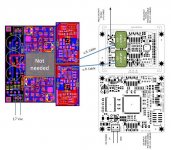
Here attached an image showing a way to connect TWTMC boards to Ian's boards (the first otion is showed).
Where I wrote "Xo adapter ???" means that we need Ian's support to understand what his adapter can accommodate. U.fl. connector if possible or direct soldering on XO adapter pads.
The document "Ian_Form_Example.pdf" is an example that show how to fill the document "TWTMC Parts Options & Assembly Service" provided from Phil.
As soon as I'll find a little free time, I'll try to publish some pictures (next days).
Here attached an image showing a way to connect TWTMC boards to Ian's boards (the first otion is showed).
Where I wrote "Xo adapter ???" means that we need Ian's support to understand what his adapter can accommodate. U.fl. connector if possible or direct soldering on XO adapter pads.
The document "Ian_Form_Example.pdf" is an example that show how to fill the document "TWTMC Parts Options & Assembly Service" provided from Phil.
Attachments
Cant send the TWTMC Parts Options & Assembly Service unless i check the D and D options wich I dont use..
Thank you for this usefull information.
I've added a "No" option for each D&D Section Options in the form.
Be careful while filling.
Thank you Andrea for your input

Regards
Phil
Last edited:
Here attached an image showing a way to connect TWTMC boards to Ian's boards (the first otion is showed).
Where I wrote "Xo adapter ???" means that we need Ian's support to understand what his adapter can accommodate. U.fl. connector if possible or direct soldering on XO adapter pads.
The document "Ian_Form_Example.pdf" is an example that show how to fill the document "TWTMC Parts Options & Assembly Service" provided from Phil.
I think Ive seen someone soldered a u.fl connector on ian's XO adapter, that should work.
Updating my order, 25MHz is gone now.
- andrea_mori : 5 x 5.6448MHz + 2 x 11.2896MHz + 3 X 22.5792 MHz + 3 x 24.576 MHz + 1 x 45.1584 MHz + 1 x 49.152 MHz + 1 x 90.3168 MHz + 1 x 98.304 MHz + 10 x PCB + 4 x daughter board PCB
- Eldam : 1 x 5.6448MHz + 1 X 22.5792 MHz + 1 x 24.576 MH + 2 x daughter board PCB + 4 x PCB
- esgigt : 1 x 11.2896 Mhz + 1 x PCB, soldered if possible
- fralippo : 1 x 22.5792 MHz and 1 x 24.576 MHz + 2 x PCB + 1 x daughter board PCB
- mravinsky : 2 x 11.2896 Mhz + 2 x XO PCB + 1 x Daughter board PCB
- TNT : 1x22.5792MHz 1x24.5760MHz + 2 x PCB, + 1 x daughter board, all soldered if possible
- 1audio : 2x22.5792MHz 2x24.5760MHz + 2 x PCB + daughter board.
- randytsuch : 1x22.5792MHz 1x24.5760MHz + 4 x PCB + 1 x daughterboard
- myint67 : 1x11.2896mhz ,1x22.5792,1x45.1584,1x49.152 ,4 PCB ,2xdaughter board , soldered if possible
- kf_tam : 2x PCB
- BDL : 1 x 11.2896 MHz + 4 x PCB + 1 x daughter board PCB
- thorstenlarsen : 2 x 11.2896 MHz + 2 x PCB
- Zoran : 1x22.5792MHz 1x24.5760MHz + 2 x PCB, (soldered or not...) + 1 x 11.2896 MHz + 1 x PCB
- walangalam : 1 x 11.2896 Mhz + 2 x PCB
- AR2: 1 x 22.5792 MHz and 1 x 24.576 MHz + 2 x PCB (soldering not needed)
- mcluxun: 1 x 22.5792 MHz and 1 x 24.576 MHz + 2 x PCB + 1 x daughterboard (soldering if possible)
- damohpi: 1 x 11.2896 + 1x PCB unsoldered
- noizas : 2 x 5.6448MHz + 2 x 11.2896MHz + 4 x PCB
- badrisuper : : 1 x 11.2896 Mhz + 2 x PCB
- Clsidxxl: 1 x 45.1584 MHz + 1 x 49.152 MHz+daughter board + 2 x PCB -With Assembly Service
- zeta4 1x 22.5792Mhz + 1 x PCB (soldering not needed)
- chertk : 1 x 22.5792 MHz and 1 x 24.576 MHz + 2 x PCB + 1 x daughter board
- hirez69: 1 x 22.5792 MHz and 1 x 24.576 MHz + 1 x 45.1584 MHz + 1 x 49.152 MHz + 4 x PCB (soldered) + 1 x daughter board
- palmito : 1 x 45.1584 MHz + 1 x 49.152 MHz; 1 x 22.5792MHz 1 x 24.5760MHz; 2 PCBs; 2 daughter boards.
- gentlevoice: 1 x 22.5792MHz + 1 x 24.576 MHz + 1 x 45.1584 MHz + 1 x 49.152 MHz + 1*PCB
- naimster: 1x 22.5792 MHz + 1x 24.576 MHz + 2x PCB + 1x daughterboard (soldered if possible)
- zenelectro : 1 x 45.1584 MHz + 1 x 49.152 MHz + 2 x PCB's + 1 x daughterboard (soldered if possible)
- Ryssen : 1 x 24.576 MHz + 1 x PCB soldered
- flowerpot : 1 x 45.1584 MHz + 1 x 49.152 MHz + 2 x PCB + 1 x daughter board PCB
- deanoUK : 1 x 45.1584 MHz + 1 x 49.152 MHz + 2 x PCB + 1 x daughter board PCB
- Miklos: 1 x 11.2896MHz + 2 x PCB + 1 x 16.9344 MHz
- Kannan_s:1 x 45.1584 MHz + 1 x 49.152 MHz + 2 x PCB + 1 x daughter board PCB
- Acko : 1 x 45.1584 MHz + 1 x 49.152 MHz + 2 x PCB + 1 x daughter board PCB
- tuyen : 1 x 45.1584 MHz + 1 x 49.152 MHz + 2 x PCB's + 1 x daughterboard (soldered if possible)
- Malvin : 1 x 45.1584 MHz + 1 x 49.152 MHz + 2 x PCB + 1 x daughter board PCB
- Marlowe: 3 x 16.9344Mhz + 3 x 25MHz + 1 x 45.1584 MHz + 1 x 49.152 MHz + 1 x 22.5792 MHz + 1 x 24.576 MHz + 8 x PCB + 3 x daughter board PCB
- ppap64: 1 x 45.1584 MHz + 1 x 49.152 MHz + 2 x PCB + 1 x daughter board(soldered if possible)
- Superdad: 1 x 22.5792 MHz and 1 x 24.576 MHz + 2 x PCB + 1 x daughter board (soldered if possible)
- vita:1 x 24.576Mhz + 6 PCB
- bkdog 1 x 90.3168 MHz + 1 x 98.304 MHz + 2 x PCB + 2 x daughter board (soldered if poss)
- ryanj 1 x 11.2896 Mhz + 1 PCB + 1 daughter PCB
- justubes 1 x 11.2896 Mhz
- Status
- Not open for further replies.
- Home
- Source & Line
- Digital Line Level
- The Well Tempered Master Clock - Building a low phase noise/jitter crystal oscillator