true. And right now, I have a
LTC6957HMS-1
https://www.analog.com/media/en/technical-documentation/data-sheets/6957fb.pdf
between your oscillator and this something.
LTC6957HMS-1
https://www.analog.com/media/en/technical-documentation/data-sheets/6957fb.pdf
between your oscillator and this something.
yes. I can drive it with a single-ended signal. But I very much like to eliminate as much conversions as possible. Converting a differential clock to a single-ended output and then convert it back to differential is quite unnecessarily.
I imagine that you must already have a differential signal from your oscillator. Maybe I need to not solder a couple smd resistors/capacitors and add wires to them.
I imagine that you must already have a differential signal from your oscillator. Maybe I need to not solder a couple smd resistors/capacitors and add wires to them.
Last edited:
Unfortunately the sine wave output is single ended, the oscillator circuit use a bjt in differential configuration but one side of the differential is dedicated to the feedback loop.
So the only way is to use a RF transformer to convert the oscillator output to differential, you can take a look at Mini-Circuits components to find one.
BTW, if I remember correctly the LTC6957 has been tested with single ended input and it performs very well (very low phase noise).
So the only way is to use a RF transformer to convert the oscillator output to differential, you can take a look at Mini-Circuits components to find one.
BTW, if I remember correctly the LTC6957 has been tested with single ended input and it performs very well (very low phase noise).
Last edited:
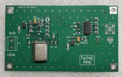
TWTMC-PPG Entry level Pierce pico gate oscillator
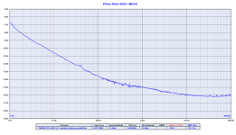
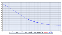
I attach a picture of the new Pierce pico gate oscillator and a couple of phase noise plots.
The TWTMC-PPG is suitable for 22/24 MHz AT-Cut crystals only.
It's a entry level oscillator provided with standard HC49 resistance welded AT-Cut crystals.
We have measured 5 crystal samples (24.576 MHz), I attach the phase noise plot of the best and the worst performer.
Since they are standard HC49 crystals (no selection from the manufacturer) the results are very different from one crystal to another, -106dBc for the worst and -116dBc for the best at 10Hz from the carrier.
Anyway it looks like they perform 10 to 20 dB better than the Crystek at the same frequency.
The 22.5792 MHz one is a few dB worse.
This is a entry level oscillator we only provide as finished board with crystal installed.
As you can see from the phase noise plots there is a lot of variability between one crystal and another therefore we cannot guarantee consistency of performance.
Attachments
Have you got PN info for first plot extending back to 0.1Hz (as per second plot)?
Thanks.
Thanks.
Last edited:
The plots are made by the Timelab program that controls the measurement with
the timepod. There is no opportunity for user error here.
The measurements down to 0.1 Hz take a small eternity because of averaging
and data collection, one would not like to suffer that unless the possible results
are worth it.
cheers, Gerhard
the timepod. There is no opportunity for user error here.
The measurements down to 0.1 Hz take a small eternity because of averaging
and data collection, one would not like to suffer that unless the possible results
are worth it.
cheers, Gerhard
Have you got PN info for first plot extending back to 0.1Hz (as per second plot)?
Thanks.
Gerhard has well explained, to get phase noise down to 0.1 Hz and below it takes hours.
Anyway as a rule of thumb you can extend the curve with a ruler to get the phase noise at 0.1 Hz from the carrier (1/f3 noise is around 30dB/decade, so you can calculate -40dBc at 0.1Hz).
Since this is a entry level cheap oscillator it does not worth.
Keep in mind that Crystek measured theirs oscillators down to 10 Hz and this Pierce pico gate oscillator has a price similar to the CCHD-957.
Last edited:
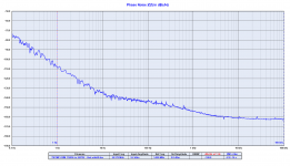
After the last tuning of the Driscoll and Differential oscillators we have measured again the phase noise of the 11.2896 MHz duplicated to 22.5792 MHz with one frequency doubler, plot attached.
It performs better than the USD 19000 MSB Femto Clock:
- at 10Hz from the carrier it's 1dB better
- at 1Hz from the carrier it's 10dB better
- at 0.1Hz from the carrier it's 7dB better
It performs better than the USD 19000 MSB Femto Clock:
- at 10Hz from the carrier it's 1dB better
- at 1Hz from the carrier it's 10dB better
- at 0.1Hz from the carrier it's 7dB better
Attachments

Last edited:
Whats the native frequency of the female galaxy clock?
The same of the duplicated, 22.5792 and 24.576 MHz.
[emoji23][emoji23][emoji23]Whats the native frequency of the female galaxy clock?
This project is an impressive amount of work andrea_mori. I am trying to determine which parameters are important for achieving good phase noise. For example, I thought that good signal purity would a have role, but this does not seem to be the case. For example the Pierce gives a reasonable account for signal distortion and low noise seen at the crystal, but does not deliver best performance. Is this due to low circuit Q etc.
Have you formulated any views on what to prioritize? There isn't much clarity from technical papers either. I am developing a low current solution and determining whether the Pierce can be bettered in this role.
Have you formulated any views on what to prioritize? There isn't much clarity from technical papers either. I am developing a low current solution and determining whether the Pierce can be bettered in this role.
- Status
- Not open for further replies.
- Home
- Source & Line
- Digital Line Level
- The Well Tempered Master Clock - Building a low phase noise/jitter crystal oscillator