MarcelvdG said:Thanks, but how does measuring how well the jitter of an AES3 or S/PDIF interface is suppressed help in assessing the effect of the quality of a master clock?
Edit: I see that my question was answered in the thread that post 2919 links to: it doesn't.
Hi Marcel.
Nobody claimed it did 😉
I wrote:
"I still find it to be a useful indicator of general problems in separate Transports/dac set-ups."
That is: in separate Transport/DAC setups, which inadvertently use the SPDIF protocol, being the case for most "semi-synchronous" (MCK inside Transport, dac PLL-locked to Transport) front-end set-ups out there.
Most certainly in the case of the now ancient 🙂 Forsell Air Reference front-end.
This was aimed at those people who still use such set-up where the Master is not located on the DAC side.
Cheers
Last edited:
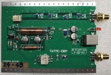
TWTMC-DBM Frequency doubler
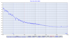
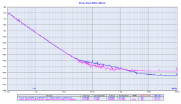
I attach a picture of the new frequency doubler and a pair of phase noise plots (5 to 22 MHz and 11 to 22 MHz).
Adding a pair of doublers to the 11.2896 MHz oscillators you can expect around -127 dBc at 10 Hz from the carrier for a 45.1584 MHz oscillator, that's an exceptional result at such this frequency.
Attachments
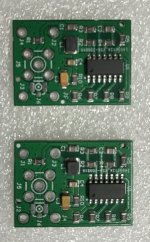
TWTMC-STS Sine to square converters
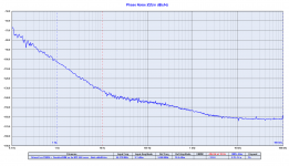
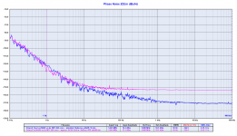
I attach a picture of the Sine to square converter (SX and DX to fit Ian's FIFO) and a pair of phase noise plots (22.5792 MHz and 5.6448 MHz).
The close in phase noise at the output of the squarer is the same of the base sine wave oscillators, only a little higher noise floor due to the noise added by the gates.
Attachments
TNT,
45Mhz, @10 Hz, -127 dBc...
8-o insane.
What you refer to still need to get squared?
If I look at the square 22MHz graph this is -125dBc
So if you want 45 out of that, according to Andrea after doubling you lose another 6dB?
so you end up for the 45Mhz in square wave at -119dB? is that correct?
is my line of reasoning correct Andrea? Please correct me if this is not the case.
Your reasoning is wrong, the sine to square converter does not increase the close in phase noise, as you can see in the plot the sine wave output 22 MHz oscillator has -125.1 dBc at 10 Hz from the carrier, while after the squarer is -124.9 dBc, so exactly the same.
You are wrong because you are looking at the base 22MHz oscillator, but if you look at the phase noise plot of the base 11MHz oscillator followed by one frequency doubler (so 22 MHz at the output) you can see -133dBc at 1 Hz from the carrier.
Then add the theoretically 6dB for one more frequency doubler and you finally get exactly -127dBc at 10 Hz from the carrier with 45.1584MHz output.
The sine to square converter only increase the noise floor but not the close in phase noise of the sine wave oscillator.
Congratulations Andrea, the results look very promising, especially the square converter for 22MHz!
The Sabre is not a delta-sigma DAC. According to White Papers, they use their own proprietary HyperStream modulator, which is very linear and noise free (>160dB!), together with further benefits.
The Sabre chips are built up of several internal (software configurable) blocks which allow them a great flexibility. Insofar, you can call them "converter systems".
The following points will clarify some advantages of this flexibility:
a) You can run them in synchronous master mode, using the I2S input (for my taste clearly better than SPDIF, without a MUX) and a standalone ultralow jitter masterclock oscillator.
...and the clock signal will be as pure as it can get.
b) It`s possible to supply up to eight parts of the chip completely independent. Every part over its own, specifically designed supply. For example ultra low noise L/R-analog supplies, digital core supplies with fast correction amplifiers etc.
Furthermore, your absolutely free, to add for example an outsourced interpolation filter, if you`re not pleased with the internal one.
These, amongst others, are the reasons, why professional and high-end gear manufacturers opt for the Sabre.
Given a (top) front-end DAC, along with an ultralow noise clock, I made the following experience:
Despite beeing a TDA1541, PCM63, AK4399 or ES9038PRO implementation, it`s the output stage, resp. I/V-converter, together with the following preamplifier/buffer, that has great impact on the resulting sound and can make a huge difference.
Last year, I had the chance to compare a TDA1541 top of the notch implementation against my highly developed Sabre.
Both played on an extraordinary high level, the differencies have been marginally and their sound was as musical as it can get 🙂
Joking aside I don't really like the sound of the delta-sigma DACs,...
The Sabre is not a delta-sigma DAC. According to White Papers, they use their own proprietary HyperStream modulator, which is very linear and noise free (>160dB!), together with further benefits.
Originally Posted by Alexiss
SABRE dac chips are not DA converter chips, they are converter systems, containing a lot of additional circuitry (SRC, MUX, DMUX, various DF's, Reclockers, switches aso).
By the time the clock signal reaches the converters, it's been heavily polluted.
The Sabre chips are built up of several internal (software configurable) blocks which allow them a great flexibility. Insofar, you can call them "converter systems".
The following points will clarify some advantages of this flexibility:
a) You can run them in synchronous master mode, using the I2S input (for my taste clearly better than SPDIF, without a MUX) and a standalone ultralow jitter masterclock oscillator.
...and the clock signal will be as pure as it can get.
b) It`s possible to supply up to eight parts of the chip completely independent. Every part over its own, specifically designed supply. For example ultra low noise L/R-analog supplies, digital core supplies with fast correction amplifiers etc.
Furthermore, your absolutely free, to add for example an outsourced interpolation filter, if you`re not pleased with the internal one.
These, amongst others, are the reasons, why professional and high-end gear manufacturers opt for the Sabre.
Given a (top) front-end DAC, along with an ultralow noise clock, I made the following experience:
Despite beeing a TDA1541, PCM63, AK4399 or ES9038PRO implementation, it`s the output stage, resp. I/V-converter, together with the following preamplifier/buffer, that has great impact on the resulting sound and can make a huge difference.
Last year, I had the chance to compare a TDA1541 top of the notch implementation against my highly developed Sabre.
Both played on an extraordinary high level, the differencies have been marginally and their sound was as musical as it can get 🙂
I attach a picture of the new frequency doubler and a pair of phase noise plots (5 to 22 MHz and 11 to 22 MHz).
Adding a pair of doublers to the 11.2896 MHz oscillators you can expect around -127 dBc at 10 Hz from the carrier for a 45.1584 MHz oscillator, that's an exceptional result at such this frequency.
Hi Andrea,
Might I ask (only for educational purpose) what the frequency mixer on “TWTMC DBM” is for?
Given a (top) front-end DAC, along with an ultralow noise clock, I made the following experience:
Despite beeing a TDA1541, PCM63, AK4399 or ES9038PRO implementation, it`s the output stage, resp. I/V-converter, together with the following preamplifier/buffer, that has great impact on the resulting sound and can make a huge difference.
I strongly agree with your statement. In my experience, in a hiend, well implemented dac, the I/V or output stage has vastly more impact on resulting sound/neutrality/musicality than the dac chip itself.
In properly implemented and optimized dacs, dac chips differences are very very subtle and have very little effect on listening pleasure...
I had both an ESS 9038pro dac and an AKM 4490 diy optimized dacs and together with my audiophile friends we had to spend hours listening A/B and with unusual concentration to find some very very slight differences between the two. But changing little details or values in output stages, the differences were huge!
Of course, each dac chip has to be implemented in a properly optimized way, you can't use the same techniques for every dac chip, if you do so the results are misleading. Each chip characters have to be mitigated and/or underlined as needed to reach right levels of detail, musicality, threedimensionality, instrument separation, etc... This does not mean to implement heavy interventions to "correct" problems caused by dac chips "shortcomings", but simply to respect dac chips technologies that are different. Few interventions - but right choices - are needed in every case. So, open-mind experimentation avoiding prejudices.
This is true, IMHO, for every dac chip, including sigma-delta, hyperstream and multibit ones.
It would be very childish and silly to think hundreds or thousands of expert audiophiles diyers implementing custom ESS dacs, AKM dacs or multibit dacs are simply "ignorants", "ultrasonics lovers", "distortion lovers", "flat sound lovers" or even "deaf" (for each other)... 😛
Not to talk about dac chips designers, who i think are much more expert and skilled than most people writing in this thread, having better measuring instruments, wider resourceas and designing possibilities, bigger testing/refining opportunities and so on (unlike many medium/low level commercial audio gears designers). In a high-tech field like da-conversion, thinking that an entire generation of dac chips designers could do sound-worsening or meaningless choices for commercial or "obsession" reasons is a bit fanciful, in my opinion
Last edited:
Hi Andrea,
Might I ask (only for educational purpose) what the frequency mixer on “TWTMC DBM” is for?
The double balanced mixer is the core of the circuit, it performs the frequency duplication.
Sorry, but I have to say again that the comparison between DACs technology is a little off topic in this thread, so please keep the discussion limited to the implementation of these oscillators with the various DAC architectures.
As I said I will start a dedicated thread about our new DACs (the Lite version is ready to test with the new FIFO), although the choice was done, the new DACs are discrete multibit (no PWM in our new design).
As I said I will start a dedicated thread about our new DACs (the Lite version is ready to test with the new FIFO), although the choice was done, the new DACs are discrete multibit (no PWM in our new design).
As I said I will start a dedicated thread about our new DACs (the Lite version is ready to test with the new FIFO), although the choice was done, the new DACs are discrete multibit (no PWM in our new design).
Ok, i'm sure your new multibit dac setup will sound SOTA wonderful and it will make optimal use of your spectacular performing clocks

The double balanced mixer is the core of the circuit, it performs the frequency duplication.
Can it mix also 2 different frequencies?
Hp
The mixer yes, the filters and amplifier /buffer optimizations - not.. It all is finely tuned for one precise frequency.
Sorry Andrea, I give back the word..
Sorry Andrea, I give back the word..

Can it mix also 2 different frequencies?
Hp
I have quickly tried Your idea about mixing the two, 10kHz shifted signals.. I had to use my HP3336 synthetizer, it has the lowest 'skirts' that I have.. But still they are at - 110dBc.
Then I did put the resulting 10kHz signal on the RTX6001..
Doh. I got back all the dirt and skirt from my synthetizer.
Spurs from power supply residuals, the skirts from the PLL. Even higher than - 80dB spurs.
Not used to it. On my Mirand dac I'm used to - 170dBc or lower floor with very few 'features'. Applying Your fantastic analysis software, 4M or 8M point FFT. It's like an electronmicroscope into the jitter world of a dac..
But the mixing procedure works, in all case.
The mixer yes, the filters and amplifier /buffer optimizations - not.. It all is finely tuned for one precise frequency.
Sorry Andrea, I give back the word..
Yes, LO and RF ports are wired in series and drove with the frequency to be duplicated.
Of course the filters have been tuned for each frequency.
- Status
- Not open for further replies.
- Home
- Source & Line
- Digital Line Level
- The Well Tempered Master Clock - Building a low phase noise/jitter crystal oscillator