TWTMC
From the OP (#1), the TS seemed to suggest that it was the Laptech crystal that was the real workhorse of the TWTMC.
Earlier, when prompted for References, the TS ignored the query, even shunning it. I assume -- as is often the case in "DIY" forum projects -- that the TS merely lifted the design from an electronics textbook or magazine.
OTOH, if there are some accounts -- somewhere in this overlong and messy thread -- of folks using any TWTMC circuit w/o Laptech, provide links as necessary.
I don't get it.I would do my research and decide the best choice and implement them. ...
Now I would say there is quite a bit of DIY involvement in the implementation of these clocks.
From the OP (#1), the TS seemed to suggest that it was the Laptech crystal that was the real workhorse of the TWTMC.
Earlier, when prompted for References, the TS ignored the query, even shunning it. I assume -- as is often the case in "DIY" forum projects -- that the TS merely lifted the design from an electronics textbook or magazine.
OTOH, if there are some accounts -- somewhere in this overlong and messy thread -- of folks using any TWTMC circuit w/o Laptech, provide links as necessary.
Maybe if we slave the USB to I2S source before the Fifo with the prg TWTMC Masterclock, the Fifo would have a good enough timing before he sends through the Ian's clock with TWTMC adaptators on it ?
Unfortunately it does not help, the only way is a FIFO buffer slaved to the WS/LRCK clock avoiding these crucial signals to cross FPGA/CPLD and feeding directly the DAC.
I don't get it.
From the OP (#1), the TS seemed to suggest that it was the Laptech crystal that was the real workhorse of the TWTMC.
Earlier, when prompted for References, the TS ignored the query, even shunning it. I assume -- as is often the case in "DIY" forum projects -- that the TS merely lifted the design from an electronics textbook or magazine.
OTOH, if there are some accounts -- somewhere in this overlong and messy thread -- of folks using any TWTMC circuit w/o Laptech, provide links as necessary.
You must read before claim …. "When the crystal makes the difference"
The Well Tempered Master Clock - Building a low phase noise/jitter crystal oscillator
RN60 perhaps, certainly not RN55... YMMV... high frequencies are not the ones we are confident with.Mine prefered resistors Dale RN & Shinkoh only through hole.
Cheers
Felipe
I think it's fair to say Laptech is an MVP. And Andrea's work to develop the circuit. But like everything, implementation can make something great a little better.I don't get it.
From the OP (#1), the TS seemed to suggest that it was the Laptech crystal that was the real workhorse of the TWTMC.
Take your TDA1541A. It is the MVP. There are thousands of pages of discussion on this site searching how to perfect it beyond the Phillips reference design used by all the CDP manufacturers.
@Joseph K & Merlin: Thanks for briefly suggesting SMD resistors that could be "excellent". I will, however, take the liberty of leaving it here - only meant to be a brief digression to the thread subject ;-) - yet to Merlin say that my experience (to my ears that is) is that the RN65E is the best sounding of the Vishay RN series (15ppm tempco).
Again to my ears they are clearly more open, harmonious, and "fluid" sounding than the regular C & D types. I haven't listened to the RN55E, RN60E, or RN70E, though, but given that resistor distortion drops 6 dBs per doubling of resistor rated wattage (for the same dissipated power) the 65E has been a preferred choice for a medium price resistor.
And I also am not aware of an SMD version of these resistors ...
Cheers,
Jesper
to get the same power dissapation as an RN65 you need a large chip as in 1206. And many SMT resistors are thick film, the modern version of a cheap carbon comp resistor. You can get really good SMT parts for $$$. Still a leaded RN65 will handle mor real power.
However for terminating a transmission line on a PCB a small SMT resistor is ideal since you won't have big discontinuities in the line. I would look for a thin film SMT resistor. Here is much better discussion than I could possibly contribute: Terminating high-frequency signals in a PCB layout design? Keep in mind that the fast transitions that make for the lowest phase noise devices also make for the most EMI/RFI.
However for terminating a transmission line on a PCB a small SMT resistor is ideal since you won't have big discontinuities in the line. I would look for a thin film SMT resistor. Here is much better discussion than I could possibly contribute: Terminating high-frequency signals in a PCB layout design? Keep in mind that the fast transitions that make for the lowest phase noise devices also make for the most EMI/RFI.
RN60 perhaps, certainly not RN55... YMMV... high frequencies are not the ones we are confident with.
RN65
Re: sine to square converter,
what is the typical output of standard XOs?
edit: that would be square output for CMOS XO?
When would a sine output be needed to not incorporate the converter into the XOs?
what is the typical output of standard XOs?
edit: that would be square output for CMOS XO?
When would a sine output be needed to not incorporate the converter into the XOs?
Last edited:
Usually the output of an XO is sine wave, but there isn’t a standard.
You Don’t need to include the sine to Square converter if you have to multiply the frequency, so these new oscillators doesn’t incorporate the converter.
You Don’t need to include the sine to Square converter if you have to multiply the frequency, so these new oscillators doesn’t incorporate the converter.
RN65
yup, RN65...little bulky though.
never liked those RN55, I never thought I could hear it in an analog stage but I did 😱 and removed it from a pre with great sucess.... I much prefered the Yageos to the RN55.
If you have monney, time to source, time to wait, Rhopoint and some Vishays are good. Never had problem with Sussumu however but non long extended try, just a dac tested with it in the I2S path. Okay let's return to the main subject, sorry for the disgress.
Thanks for the response. Unfortunately I've missed that when I wrote my post. In the meantime I searched for some information and got it.For crystal at the frequency of my interest (16.9344MHz) mqo is 10pcs.@Andrea: Thanks again for your clarification. I assume "no further questions" ;-) - look forward to hearing more in due time ...
@Hifoli: Hi & thanks for your feedback ...
WRT digital transmission resistors my personal thoughts about this are:
* That source resistors ideally should be placed as close as practically possible to the sending end. This will reduce the capacitance seen by the sending IC output ("unlimited bandwidth into a capacitance" - the trace + ground plane capacitance) and thus reduce the peak current drawn from the sending IC output. On the other hand it is not that clear to me what the advantages of using a receiving resistor may be? ... I reckon it may reduce a possible send-resistor + trace impedance mismatch reflection but again it takes up space where often space is limited.
WRT SMD resistors: Are you using thin film or thin foil SMD resistors? If thin foil I'd be interested in hearing about which one.
@tom59hifi: I think I will take the liberty to answer somewhat on behalf of Andrea ... If you read a couple of pages back you will see that Andrea mentions starting a GB likely before the end of June. This is a.o.t. to be able to order from Laptech even with their minimum orders.
@merlin: Thanks for the tip on tantalum nitride. However, the PFC resistor I mention is exactly tantalum nitride and to my ears they are not as open and "alive" as e.g. Charcroft CAR or Vishay RN65Es ... Might you have some other TN resistor in mind?
Have a good day!
Jesper
As things stand, it is almost certain that I'll take that amount cause I'm in hurry.
As things stand, it is almost certain that I'll take that amount cause I'm in hurry.
Their lead time used to be 6-8 weeks so I hope you're not in too big of a hurry.
Starting the new GB
Although we are doing the last fine tuning of each device to reach the best performance as possible, I decided to start the new GB to understand if there is enough interest to overcome the Laptech's MOQ for each crystal.
I will publish soon the indicative price of each crystal, bare PCB, finished board an so on in the GB thread located at The Well Tempered Master Clock - Group buy
The BOM and the assembly instructions of each device will be published in the main thread as soon as we have ended test and tuning.
Crystals and PCB prices are higher than previous batches, there are at least 3 reasons:
- the previous batches I lost money for some crystals, for example SC 5/6 MHz was quoted at a price from Laptech but when I received the invoice the final price was 30% higher
- high developing cost of the new devices due to several iterations (PCBs, components, assembly) and mostly the cost of the measurement gears
- some fiscal reasons
Obviously I have not considered the time we spent to develop these devices (years), this is our gift to the audio community.
The new GB includes:
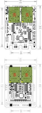
- New Driscoll XO (SC-Cut crystals from 5.6448 MHz up to 24.576 MHz)
- New Differential XO (SC-Cut crystals from 5.6448 MHz up to 24.576 MHz)
- New Pierce XO (AT-Cut crystals from 5.6448 MHz up to 98.304 MHz)
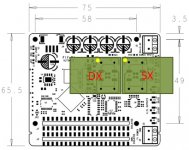
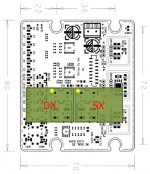
- New Frequency Doubler (5/6 MHz to 11/12 Mhz, 11/12 MHz to 22/24 Mhz, 22/24 MHz to 45/49 Mhz, 45/49 MHz to 90/98 Mhz)
- New entry level Pierce gate based XO (AT-Cut crystals 22.5792 MHz and 24.576 Mhz only)
- New Sine to Square Converter (all new XO except the Pierce gate based are sine wave output)
- New Low Noise Regulator to supply all the above XO (except the Pierce gate based)
Coming soon:
- LiFePo4 batteries supply system
- FIFO buffer with I2S and PCM output
- a pair of discrete DAC
Although we are doing the last fine tuning of each device to reach the best performance as possible, I decided to start the new GB to understand if there is enough interest to overcome the Laptech's MOQ for each crystal.
I will publish soon the indicative price of each crystal, bare PCB, finished board an so on in the GB thread located at The Well Tempered Master Clock - Group buy
The BOM and the assembly instructions of each device will be published in the main thread as soon as we have ended test and tuning.
Crystals and PCB prices are higher than previous batches, there are at least 3 reasons:
- the previous batches I lost money for some crystals, for example SC 5/6 MHz was quoted at a price from Laptech but when I received the invoice the final price was 30% higher
- high developing cost of the new devices due to several iterations (PCBs, components, assembly) and mostly the cost of the measurement gears
- some fiscal reasons
Obviously I have not considered the time we spent to develop these devices (years), this is our gift to the audio community.
The new GB includes:
- New Driscoll XO (SC-Cut crystals from 5.6448 MHz up to 24.576 MHz)
- New Differential XO (SC-Cut crystals from 5.6448 MHz up to 24.576 MHz)
- New Pierce XO (AT-Cut crystals from 5.6448 MHz up to 98.304 MHz)
- New Frequency Doubler (5/6 MHz to 11/12 Mhz, 11/12 MHz to 22/24 Mhz, 22/24 MHz to 45/49 Mhz, 45/49 MHz to 90/98 Mhz)
- New entry level Pierce gate based XO (AT-Cut crystals 22.5792 MHz and 24.576 Mhz only)
- New Sine to Square Converter (all new XO except the Pierce gate based are sine wave output)
- New Low Noise Regulator to supply all the above XO (except the Pierce gate based)
Coming soon:
- LiFePo4 batteries supply system
- FIFO buffer with I2S and PCM output
- a pair of discrete DAC
hello,
First, thanks for the slow coocking to you & "We", it is "gage" of quality & good taste.
A question please : is the frequency doubler works individually for each frequency family ? For illustration : can it x2 a 5.6 M hz and 24.5x2 on the same board ? In instance to work with Red book and choose the trade off one like most according the frequency family.
according to the price, whished to add with what I already have :
whisch list : first Xtal as manly asked : if compatible FifoPi first gen and the board needed : a 24 SC cut -whished to work with doubler but first want the fifoPi to work with the discroll and the 5 Mhz SC cut- If not possible second family frequency wish will change according what is possible between boards.
- New Discroll for the Sc-cut
- Pierce gate to coock better the AT-Cut
- New Sine - if needed for Iancanada layout from the first standalone Fifo to the compact FifoPi-
How the new Pierce for AT-cut vs the former Discroll for AT-cut please - in order to stack on the first Clock board from IanCanada? Could help me to push the trigger or not : don't buy double if former is good enough.
Many thanks to the team for all the work.
A wisch : i it simple to have the raw individual measurment of each SC-cut one purchase ?
best regards
edit : what quicly are the voltage needed for each board in order to know if the first gen PS boards are still compatible or not ?
Last edited:
hello,
First, thanks for the slow coocking to you & "We", it is "gage" of quality & good taste.
A question please : is the frequency doubler works individually for each frequency family ? For illustration : can it x2 a 5.6 M hz and 24.5x2 on the same board ? In instance to work with Red book and choose the trade off one like most according the frequency family.
according to the price, whished to add with what I already have :
whisch list : first Xtal as manly asked : if compatible FifoPi first gen and the board needed : a 24 SC cut -whished to work with doubler but first want the fifoPi to work with the discroll and the 5 Mhz SC cut- If not possible second family frequency wish will change according what is possible between boards.
- New Discroll for the Sc-cut
- Pierce gate to coock better the AT-Cut
- New Sine - if needed for Iancanada layout from the first standalone Fifo to the compact FifoPi-
How the new Pierce for AT-cut vs the former Discroll for AT-cut please - in order to stack on the first Clock board from IanCanada? Could help me to push the trigger or not : don't buy double if former is good enough.
Many thanks to the team for all the work.
A wisch : i it simple to have the raw individual measurment of each SC-cut one purchase ?
best regards
edit : what quicly are the voltage needed for each board in order to know if the first gen PS boards are still compatible or not ?
The frequency doubler has different components for each frequency, capacitors and inductors used for filtering are related to the frequency.
About the FifoPi clock frequency limit you should ask Ian.
The new Pierce gate based comes only as finished board with crystal 22/24 MHz installed, no bare PCB or finished board without crystal.
The new discrete Pierce for AT-Cut crystals has to be tuned and measured, please be patient.
The individual measurement service is provided as an option.
The New DRIXO, EXO and PXO need a clean power supply, from 12V up to 18V (batteries suggested).
I'm patient, no prob., Tango.
Understood, Roger.
Not sure i understood what was the Transformers Kit though, Over !
Understood, Roger.
Not sure i understood what was the Transformers Kit though, Over !
- Status
- Not open for further replies.
- Home
- Source & Line
- Digital Line Level
- The Well Tempered Master Clock - Building a low phase noise/jitter crystal oscillator