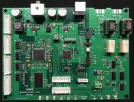
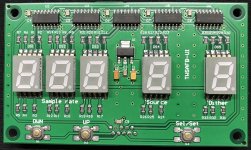
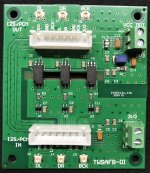
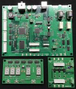
Sck is reclocked by the Fpga, exactly like all other fifo buffer and can be optically isolated, so no problem with 1794, 1704 and so on. BTW for the Dacs that switches on Lrck here there is a benefit: this signal does not cross the Fpga, it comes directly from the master clock.Andrea, the DDDAC group is using the FiFoPi to re-clock the signal for the DAC with good succes, specially when your clock is involved. I saw this topic, which looks like a FiFoPi, with the different perspective, that you claim that the word clock is the most important and is the only signal being reclocked (?) This might be the case with the PCM63, but not for the PCM1794. I just wanted to state that here before anyone thinks this re-clocker can be used with a DDDAC.
Unless I missed the point and it is not only the LR clock being re-clocked?
May be you can elaborate on the difference with the FiFoPi?
thanks!
Doede
oh by the way, in the PCM1794, ultimately the SCK is the most critical. The SCK determines when the oversampled output updates, so reducing jitter on that line would reduce discrepancies on the output
Sck is reclocked by the Fpga, exactly like all other fifo buffer and can be optically isolated, so no problem with 1794, 1704 and so on. BTW for the Dacs that switches on Lrck here there is a benefit: this signal does not cross the Fpga, it comes directly from the master clock.
Great ! Thanks for the elaboration 🙂
In order to clarify how this device works I attach a schematic block diagram.View attachment TWSAFB_Block_Diagram.pdf
In order to clarify how this device works I attach a schematic block diagram.View attachment 816336
Andrea, Looks like a very good solution.
Looking at block diag, why do you need dithering?
Also what is latency / time delay through FIFO?
Also, is there provision for L and R justified PCM PCM179x uses R for DF bypass mode)
Great work.
TCD
Last edited:
Andrea, Looks like a very good solution.
Looking at block diag, why do you need dithering?
Also what is latency / time delay through FIFO?
TCD
Dithering is an option to avoid data truncation when input bit depth is bigger than output bit depth (eg. from 24 bit input to 16 bit output). Anyway dither can be excluded and data will be truncated.
We are using 8MB SRAM so the latency is in the range 0.5-0.7 seconds.
Hi Andrea,
Will you consider adding multi-channel support for your fifo? I wish the digital cross over will work on it.
Poting
Will you consider adding multi-channel support for your fifo? I wish the digital cross over will work on it.
Poting
Hi Andrea,
Will you consider adding multi-channel support for your fifo? I wish the digital cross over will work on it.
Poting
Not in this version, maybe in a new release.
This version provides support for dual mono and balanced DAC.
Has someone get off the crystal can inside the Crysteq :see pictures given by Hanze Kroyne in Iancanada fifo thread or the long TDA1541 John's one (can't remenber which one ?
For whom having the Cryteq maybe they can take this crystal inside the squared case of the CCHD-95x serie hoping Crysteq sorted them ? I mean in order to be used on an Andrea Mori & We pcb ???
Andrea, could it give somethin less good than the AT-Cuts but better than without the Crysteq on board osci ??
Has someone get off the crystal can inside the Crysteq :see pictures given by Hanze Kroyne in Iancanada fifo thread or the long TDA1541 John's one (can't remenber which one ?
For whom having the Cryteq maybe they can take this crystal inside the squared case of the CCHD-95x serie hoping Crysteq sorted them ? I mean in order to be used on an Andrea Mori & We pcb ???
Andrea, could it give somethin less good than the AT-Cuts but better than without the Crysteq on board osci ??
Hi diyiggy, I believe that inside the Crystek oscillator there is an ordinary crystal, not so fine to be used in other circuit. So I think it does not worth.
Andrea
Implement a volume control with dither?
//
No digital volume control, the only purpose of dithering is to avoid truncation when input bit depth is larger than the output bit depth (eg. 24 to 16 bit). Anyway the truncation is available setting the dither option to 0 (off).
Thank you Andrea,
Makes sense when I see the cost, measuring and sorting out the crystal might be too expensive for a factory at thi cost. PulsarClock or JackoHomo were sorted sorted out some cheap crystals... but I think they may be found 1 for 100 or 1000 units bought... long, expensive and fastidious...
I was thinking of a cheap sorting out with the CHHD-957, but indeed it must be the tinny layout of the embeded "osci" pcb that help... In the same time the NDK seems to measure as good as the Crysteq for less. For the few tests I made by try & error & listening (find the culpritt) the CHHD-957 was certainly oscillating with too much little capacitance decoupling outside the can... the result was way better with a non class II ceramic, nore a class I but a smd PET or PEN cap same 0802 size inductance from 0.1 uF to 1 uF capacitance for the bypass gnd 😱 (highly advised for whom using the Crysteqs on a IanCanada board for instance 😉.... at least to my beloved ears and musicians' friends)
Well let's go back to our sheeps... Colpritts... oups, Discrolls (sorry!) and Laptechs

Last edited:
Hi, this looks great!
quick question though 🙂
If I design an input on my dac for your reclocker (4 x pcm1794a in Mono left and 4x in Mono Right).
Would you recommend me to make input connections „bclk, lrck, dataRight, dataLeft“ and just split the bclk trace on my board or can/should I use one bclk output from the second output of your board and make „bclkRight, bclkLeft, lrck, dataRight, dataLeft“ Inputs on my side?
Thanks in advance for your help and work, can’t wait to get my hands on your new board and clocks 😉
Greetings Oli
With so many DAC chip to feed I suggest splitting bit clock on your input board, where you can control better the trace impedance.
Thanks, I’ll do that then!
Quick follow up: I guess that means that even if it is possible to use both i2s outputs at the same time, say one output for my left and one for my right side, probably wouldn’t bring any more benefits than good impedance matching (jitter/performance wise)
Quick follow up: I guess that means that even if it is possible to use both i2s outputs at the same time, say one output for my left and one for my right side, probably wouldn’t bring any more benefits than good impedance matching (jitter/performance wise)
- Home
- Source & Line
- Digital Line Level
- The Well synchronized asynchronous FIFO buffer - Slaved I2S reclocker


