Great ! I can now figure out the whole thing Eivind !
Does this board works ? Have you heard about it ?
Thank you very much !
Roberto Berner
Does this board works ? Have you heard about it ?
Thank you very much !
Roberto Berner
I do hope I don’t confuse you more than I have before.
I have built a Mimesis, but never heard about Nemesis. Is that an improved version?
Ha Ha Ha ! Ohh I'm sorry !  YES, you are right my friend: Mimesis, from now own this will be.
I wish I could ! I doubt it.
Thank you very much.
Roberto Berner
YES, you are right my friend: Mimesis, from now own this will be.I wish I could ! I doubt it.
Thank you very much.
Roberto Berner
Goldmund clone
obiwankenobi
That was nice to hear.
Yes, this is the PCB I used for both my Goldmund clones and it worked perfect for both +/- 40 and +/- 60 VCC ; and +/- 60 and +/- 80 VCC.
Eivind Stillingen
obiwankenobi
That was nice to hear.
Yes, this is the PCB I used for both my Goldmund clones and it worked perfect for both +/- 40 and +/- 60 VCC ; and +/- 60 and +/- 80 VCC.
Eivind Stillingen
Thank you for this information.
Now the important question here: the protection circuit is the same one ?
Now the important question here: the protection circuit is the same one ?
Goldmund clone
Sorry, I wrote this three oclock night-time
While leaving the Nemesis 9.2 thread, Nagy started a new project with Nemesis 3.
In one of the posts Nagy wrote that “Nemesis 3 is 95% similar to Nemesis 9.2”. As far as I can see this was the main differences:
I do hope that this Goldmund project will not be a Nemesis for obiwankenobi
Eivind Stillingen
YES I was thinking about that ! It is 11:06 pm here in Buenos Aires, you should get some rest, I appreciate your effort, no need to reply so soon Eivind.
Still don't know your opinion about protection and this Nemesis 9.2 . . . maybe tomorrow.
If I can get this working I will post results, I like to share, it will take time however.
Thank you again Eivind
Roberto
Still don't know your opinion about protection and this Nemesis 9.2 . . . maybe tomorrow.
If I can get this working I will post results, I like to share, it will take time however.
Thank you again Eivind
Roberto
Thank you so much ! Eivind you should sleep !!!
I will put all this together and see what I can do.
It is a good picture !
Good dreams my friend !
Roberto
I will put all this together and see what I can do.
It is a good picture !
Good dreams my friend !
Roberto
it is the same board I've got...
not finished yet but getting there. there are several members here who built one, no one complaint about the protection circuit to my knowledge.
stig
not finished yet but getting there. there are several members here who built one, no one complaint about the protection circuit to my knowledge.
stig
obiwankenobi
Here is the BOM list for Goldmund 9.2. I have checked this list with your "silksreen copy" where the values are written and I am sure the the Protection cicuit on Mimesis 3 is identical to Mimesis 9.2 (as the rest of the PCB). I can now see that it is possibel to mount source resistors on your PCB. Nagy was very negative to source resistors.
Eivind Stillingen
Attachments
Thank you so much for all this material Eivind 🙂!
I think I have the tools now.
I will put it all together.
My wife and I have been looking this nice place where you live in Norway, 25 Km from Oslo. Beautiful place !
Thank you so much.
Roberto Berner
I think I have the tools now.
I will put it all together.
My wife and I have been looking this nice place where you live in Norway, 25 Km from Oslo. Beautiful place !
Thank you so much.
Roberto Berner
L58a post 361
Hi Wahab,
A little off topic here...hobe its ok!
In short...L58a, of which you have made a schematic drawing in post 361 on page 37, I would like to ask you, if you could add the missing balance pot in the input differential stage and the 330R VR702a pot, which I think is for idle-adjustment.
You have added a connection between Q705a and Q706a from the resistor R705a which is missing on the L58a schematic....the connection is there from the negative rail supply and R715a between Q707a and Q708a.
The servo feed-back opamp is not included in your drawing either, and I assume that you made the L58a drawing for simulating and because you liked the topology?
I own the L58a and have with luck repaired the psu. The L58a is one of the best sounding amplifiers I have listened to...and there are several amplifiers here🙂
Autodidact electronic man. rgds. Kim
amateur site: TUBEAMP
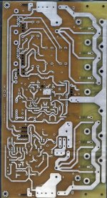
Eivind (Lilya) I have compared de copper of my Goldmund 3 PCB version against the neat schematic of the GN 9.2 protection board.
The result is that the complete protection schematic circuit that you provided complies with the copper traces of the PCB.
Just found one single error in the schematic which is that the electrolytic capacitor named C4 is reversed. The positive lead should be connected to the +80 VCC line ( +60 V in GM3 ).
Also (this is not an error) capacitors C6 10 nF and C7 47 pF are paralleled in the schematic to form one single 15 nF capacitor, which in my PCB is just a single capacitor.
IMO the protection circuit then matches the copper perfectly well.
I am now checking the rest of the amplifier schematic. The only problem here is that the part numbering of the amplifier overlaps the numbering of the protection circuit, later I will try to fix this.
Copies of both provided GN 9.2 protection schematic and my version of PCB GN3 uploaded.
Kind regards
Roberto Berner
Attachments
Obi.
try changing c5 to 10pF. in amp.
protection D4 D6 I think is 4004 from memory, maybe someone could confirm?
otherwise it looks ok to me. same as I'm building
regards
edit: mine have the correct orientation printed on the board regarding c4
try changing c5 to 10pF. in amp.
protection D4 D6 I think is 4004 from memory, maybe someone could confirm?
otherwise it looks ok to me. same as I'm building
regards
edit: mine have the correct orientation printed on the board regarding c4
Last edited:
Thank you oiphy, why change that value of C5 to 10 pF ?
The C4 is reversed in the schematics but it is Ok in the PCB.
The diodes are 1N4148.
Thank you !
Roberto
The C4 is reversed in the schematics but it is Ok in the PCB.
The diodes are 1N4148.
Thank you !
Roberto
Well dear friends ... here is a draft that includes both circuits.
Of course needs revision, I know it is a little tight, but I just wanted to have it all in a single A4 sheet for better understanding the interconnection.
Schematics are redundant in some components - corrected now. protection capacitor C4 is now OK polarized.
I have to figure out how to renumber parts so not to destroy the originals that belong to GM3 and GM 9.2 , both schematics overlap component annotation and my PCB version silkscreen does not show parts numbering at all 😡
I think that I will add some prefix to those components that belong to the protection circuit ... any ideas ?
PDF uploaded for you so welcome comments, please excuse my drawing and any possible errors.
Greetings to you all.
Roberto
Attachments
- Home
- Amplifiers
- Solid State
- The Very Best Amplifier I Have Ever Heard!!!!