
rush yeah the color certainly err a touch feminine maybe ?
I wanted the case so too bad all this is going into magic "it-will-come-in-handy-someday" box - I say magic because nothing ever comes out again!
The case and heatsinks are worth $500 or more.
Any chance I could buy one of these to gut? Who made it?
The color is OK with me, just that it wasn't black to dissipate heat more efficiently. I actually like the color.
I have an unfinished F5T sitting because I hate putting a case together from scratch and I bought USA heatsinks and mounted everything, but no case yet.
Rush
Purchased from these fine purveyors of audio exotica from the east (N I'm not making this up...):
Cattylink
ymmv tremendously
WOW $615 shipped to USE in 220 or 230 VAC only.
What rail voltage does it run at and how much will the heatsinks dissipate, do you think? Enough for a F5T (32VDC at 2.5 AMPs)
They mounted the transistors too high on the sink, should be much lower. You might be able to flip them and switch left to right.
Rush
look to me to be closer to a grand landed in the US so wont be a cheap date i dont think. Maybe buzz will get a line to the empty cases so fingers crossed...
Re the heatsinks - i don't know how much they will dissipate but will let you know once buzz's pcb get here. He's laid out the PCB for optimal heat dissipation and I'll tap holes 1/3 of the way up on the sink. (Anyone have a line on suitable taps/drillbits/hex-screws available on line?)
This is the only case option I have at the moment so its gonna get shoehorned in here either way. The preamp/selector bits I will play around for a standalone preamp maybe - there won't be space to keep it in here anyway once the big toroid goes in. Stay tuned chaps...
I am suspicious that the amp and heatsinks are all glitter with no serious engineering behind them. Their website spec sheet for the amp doesn't inspire confidence, particularly given the measurements that kasey197 shows in post #120. Someone needs to strip down the chassis and do actual heatsink measurements.
I am suspicious that the amp and heatsinks are all glitter with no serious engineering behind them. Their website spec sheet for the amp doesn't inspire confidence, particularly given the measurements that kasey197 shows in post #120. Someone needs to strip down the chassis and do actual heatsink measurements.
But it's pretty!!! Wife will love it!
Rush
Funny that ... the shiny new turbo grill on my patio also usually attracts far more attention that my much-worked-on marinade 😀
In post #103 I made some observations about the Valorous design, in particular about the effectiveness of the capacitors across the source resistors. I revisited some simulations I did a while back of a circlotron and an F5-like push-pull amplifier. I was looking for ways to reduce H3 (and other odd harmonics) by eliminating source degeneration. With ordinary push-pull output stages, reducing degeneration also reduces odd harmonics, but not with the circlotron output stage. I have not seen an explanation for this, but I believe it is because of the difference in global feedback between to two topologies. With push-pull, H2 is mostly cancelled in the output stage itself, before being sent to the global feedback network. In the circlotron, uncancelled single-ended outputs are sent to two global feedback networks, which convert H2 into higher harmonics via feedback.
What I conclude from this is that in a circlotron minimizing degeneration only serves to increase open-loop gain (OLG) but will not significantly improve distortion. The most effective ways to reduce distortion in the circlotron is by using lots of DC bias current and lots of feedback.
If others are interested, I could put together some simple simulations that illustrate these points.
Hi lhquam - interesting stuff! I'm a bit preoccupied putting the amp together right now on Buzz's beautiful PCBs. They just got here - I'm stuffing them and also intend to try a few interesting parts (some SMDs for the ip, SICs for ops) to see what we get. Multiple output pairs are also on the to-do list. Along with cap/no-cap. I'm not wedded to anything in particular....and my takeaway on this is there's probably no inherently superior topology - most of these things seem to revolve around fb amount (whether thru degeneration or loop), bias/heat levels, FB type (CFB vs VFB), # of devices that you're willing to accept, measured distortion targets & then the consequent stability issues arising. Then you have PSU complexity vs PSRR, noise, CMRR, need for balanced vs unbalanced inputs. Practical issues of parts matching/availability and most importantly - how it all sounds to you.
What you end up with depends on the choices you make for the above. At least that's what it seems like to me.
As regards the sims also check out the post i made on the distortion and nfb thread. There will also be many many folks there interested in the results! I will also try to contribute when/if I can.
Last edited:
I forgot to state that the simulations were without cascoding. When I did simulations with cascoded output FETs, the capacitors make a BIG difference. I need to do a thorough analysis using simplified output stages to understand why eliminating degeneration doesn't always help to reduce odd harmonics.
i took a look at the basic case (not cascodes) - my results do not agree with yours.
Whether complementary push-pull or circlotron,
whether with feedback or without
Getting rid of source degeneration reduces H3.
I'll get round to measuring this in the real world at some point.
Whether complementary push-pull or circlotron,
whether with feedback or without
Getting rid of source degeneration reduces H3.
I'll get round to measuring this in the real world at some point.
i took a look at the basic case (not cascodes) - my results do not agree with yours.
Whether complementary push-pull or circlotron,
whether with feedback or without
Getting rid of source degeneration reduces H3.
I'll get round to measuring this in the real world at some point.
I do not claim to fully understand what is going on, but the following might explain some of the differences in our results. My non-cascode results were for two pairs of FQA19N20C FETs rather than one pair, increasing the gate capacitances, and reducing by 1/2 the magnitude of the degeneration seen by each FET. I will put together some idealized simulations in an attempt to illustrate how the output stage topology influences distortion. Real devices have additional effects (e.g. capacitances and Early effect) the complicate the analysis and lead to more complex circuits. One step at a time.
some sim results here for those so inclined:
http://www.diyaudio.com/forums/pass-labs/132491-distortion-negative-feedback-8.html#post3627617
http://www.diyaudio.com/forums/pass-labs/132491-distortion-negative-feedback-8.html#post3627617
So... been busy playing with these amps on the nice pcbs that buzz made. I have made just one change to the scheme - adding tempco so that biasing is quicker and easier.
Without some form of temp compensation, i ended up having to wait for more than an hour each time i fired up the amp from cold. Now it gets within 90% of final bias in like 10 mins or so. yeah 😀
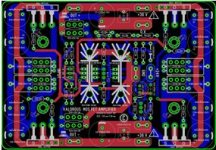
I also asked the talented Alex-MM to have another go at the layout on a compact footprint - these are off to the pcb-fab today.. take a look: He's got serious layout mojo flowing in his veins!
Without some form of temp compensation, i ended up having to wait for more than an hour each time i fired up the amp from cold. Now it gets within 90% of final bias in like 10 mins or so. yeah 😀
I also asked the talented Alex-MM to have another go at the layout on a compact footprint - these are off to the pcb-fab today.. take a look: He's got serious layout mojo flowing in his veins!
Attachments
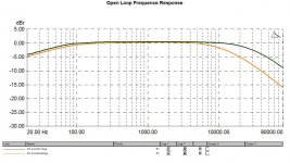
One of the more liberating things I did when developing the amplifier was to poke around with the feedback loop opened. So open loop.
I was struck particularly by the wide the open loop response and I think goes some way to explaining it's rather excellent and open sound.... This is with a pretty decent 60db open loop gain mid band....I think this is better for audio that the 110db OLG with 10 or 100 hz rolloff points like you get with many opamps.
I was struck particularly by the wide the open loop response and I think goes some way to explaining it's rather excellent and open sound.... This is with a pretty decent 60db open loop gain mid band....I think this is better for audio that the 110db OLG with 10 or 100 hz rolloff points like you get with many opamps.
Attachments
Last edited:
Wouldn't have come this far without your help Buzz so thank you !
Plan is to proof the changes and then I'll publish everything in one go with build guide and BOM for the two pcb options depending on what chassis people have. One is your long board for the store chassis and another the square one above.
Maybe a very small GB to include the exotic parts version.
Plan is to proof the changes and then I'll publish everything in one go with build guide and BOM for the two pcb options depending on what chassis people have. One is your long board for the store chassis and another the square one above.
Maybe a very small GB to include the exotic parts version.
Last edited:
- Status
- Not open for further replies.
- Home
- Amplifiers
- Pass Labs
- The Valorous Amp - A modest aggregation of pass inspired ideas