It's a looking very promising Tony
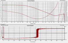
The phase response seems to be indicating that there's a resonance/instability somewhere about the 30kHz area and ever tho it's well down, it'd be good to see what's producing it - it's not the power supply?
Freq response seems pretty spot on and the slopes are also excellent - the relatively high 30Hz roll of in the bass is probably a function of cap size/gate stopper
The impulse response looks fairly free from over-shoot but is a bit on the slow side about 2msec - perhaps overdamping in the gyro?
Pretty bloody good for a new pcb and circuit prototype - congrats.
This will indeed be interesting to hear what it sounds like.
It could be the power supply... could also be the pc. Might be an idea to try with the laptop running off battery. (edit I probably should check that 12V is ok for the B1 parts of the circuit first!)
The other thing I could do is hook up a couple of SLA's and run it of +- 12V battery. The power supply does have a whopping big cap (and only 1/3 ohm damping resistor) so it could well be oscillating at a low frequency. The 30Khz glitch is there just measuring the SC with floating input though, so I think it is something airborne that is being picked up. The synergy was disconnected and powered off for the measurement in the blue trace.
Tony.
Last edited:
Yeah, he battery will get rid of any question about the supply - an easy one.
I think the 30kHz is either a problem with part of the cct somewhere (ie 180* change in phase response), or as you mentioned, might be getting picked up by the input test leads - is it worth adding 20kR loading resistor to the output plug?
Another thing might be worth trying, is to pull one end of the resistor feeding the gyrator and see if that 30kHz peak disappears - perhaps a resonance in the gyrator?
I think it's still definitely worth a good listen ..... I'm dying to know!
ok definitely ruled out the power supply. Just ran with 2 12V SLA's in series and exactly the same result.
I'm heading for bed. Might have a chance to play tomorrow. Have guests tomorrow evening so nothing tomorrow night.
Tony.
I'm heading for bed. Might have a chance to play tomorrow. Have guests tomorrow evening so nothing tomorrow night.
Tony.
Tony ,I was reading about your FDNR experiments and wondering if I can use it as a low pass filter for POST DAC filtering?
Interesting...im a novice so ive not seen that circuit.
If i take a wild guess (please correct me if I'm a dope) :
1/ the FDNR is not unity gain?
2/ the gain required is actually quite high?
3/ does that inherently result in some instability? I.e. OLG & GBW?
4/ If you posted a link about FDNRs then disregard the above, and could you kindly remind me? Interesting stuff.
5/ if 1-3 are even partially correct (I'm guessing) then the choice of op amp would probably be quite critical as you've noted.
Last edited:
Yes I think you are on the money Mondo.
Kinko, the opamp itself does not change the filter slope, but the characteristics as mondo says, do affect it's performance. There are actually only two components that affect the filter slope for a 2nd order slope. If you look at only the first FDNR above in the diagram they are the 3.09K resistor and the 3.4K resistor.
Think of the 3.09K as being the inductor, and the 3.4K as being the capacitor in a normal passive circuit. The rest are just components that make that work. If you change the values of the caps then the values of the resistors must change as well. If you changed to 100nF caps you would need to drop the resistors to 309 ohms and 340 ohms (too low). The 2K resistors you can make whatever you want. you could make them 5K 10K 20K (as long as they are the same) with no impact on the slope of the filter.
I don't actually fully understand the mechanism at work in the circuit, but my hunch is that the OLG of the opamp IS important (and I think why the LM4562/LME48960 is probably a good choice (it certainly sims much better than the opa2134). The other thing that I think is very important with this circuit is the phase margin of the opamp. The phase does not continue on down to 180 degrees phase shift but instead reverses and heads on up again. In the sims it only gets back to about 60 degrees before reversing again and heading down towards -180 but I think in practice it is behaving differently.
I originally planned to use the opa2604, but had more stability problems (on the breadboard) than I did with the opa2134, which is why that is what I have been using it. Sometime this weekend I want to put the 2604 in and measure and see what the result is. I think it is much more sensitive to layout that the 2134 so I'm interested to see how it performs in comparison on the board..
mondo I don't think I've posted this link in this thread before but have posted it elsewhere http://www.ti.com/lit/an/sbaa001/sbaa001.pdf probably time I re-read it and see if I understand more this time around 😉
Tony.
this might be a bit over the top but with a horizontal 'Brown Dog' adapter, you could squeeze a couple of the OPA627s in there instead - the only 'fly in the ointment' is that the 627s 'like' the Nichicon 470uF electros for 'best bass response (IMO here, naturally!)and they're not a small cap by any means and would either have to be assembled with 'bent leads' on the top surface (offset the body of the cap a few mm) or underneath on their sides - the Nichi KZ's are a bit particular about film bypass too and I found the 'best ones' aren't propylenes (like Wima MKP, etc ) but the polyesters (MKS, etc) for treble transparency and so on - not sure about the SMD versions altho I have some Cornell D 1uF/63 SMD ones I can send up if you'd like to try them out - possibly a bit ahead of myself here ...
hehe probably (a bit ahead of yourself) James 😉
I didn't get a chance to try out the opa2604 yet. I do have a couple of measurements I did of the noise floor last night though. Quite respectable I would say 🙂
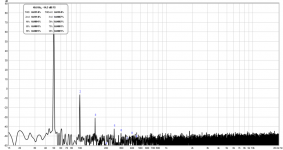
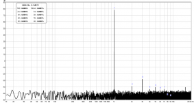
There are two measurements. First is the with the synergy connected but switched off (just to get a baseline of the connections, and what they might be picking up noise wise). and the second is with the synergy turned on.
James, I'm likely to just build this with either KZ's or Silmic II's and whatever op-amp works objectively the best. I don't trust my ears enough to make calls on whether one cap is better than another. But you are most welcome to experiment to your heart's content! I'm holding off on sending out the boards till I'm certain there isn't an issue though. The most recent measurements with holm impulse look pretty good, but ARTA and REW don't look so good. ALSO THD seems to be too high (measured not listened to), but I'm not sure if that is real or measurement method issues.
Tony.
I didn't get a chance to try out the opa2604 yet. I do have a couple of measurements I did of the noise floor last night though. Quite respectable I would say 🙂
There are two measurements. First is the with the synergy connected but switched off (just to get a baseline of the connections, and what they might be picking up noise wise). and the second is with the synergy turned on.
James, I'm likely to just build this with either KZ's or Silmic II's and whatever op-amp works objectively the best. I don't trust my ears enough to make calls on whether one cap is better than another. But you are most welcome to experiment to your heart's content! I'm holding off on sending out the boards till I'm certain there isn't an issue though. The most recent measurements with holm impulse look pretty good, but ARTA and REW don't look so good. ALSO THD seems to be too high (measured not listened to), but I'm not sure if that is real or measurement method issues.
Tony.
Attachments
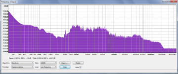
From those plots, Tony, there's not much difference between 'device - no power' and device -on' - maybe about 3dB between 70Hz - 7k, and not sure why the response suddenly goes thru the floor at about 18kHz - possibly a testing parameter?
And there doesn't appear to be any of that 'weirdo stuff' about 30kHz where the phase response (#98) 'goes positive' then peaks about 42k then 'nose-dives' sharply - if this is just a measurement/testing anomaly or an indication of an undesirable circuit resonance (emphasised in Walt's original articles, if my memory is ...)
Have you got around to assemble the high pass circuitry to see if it also has a similar problem with the phase/freq response about the 30k area?
A high freq resonance (if that's what it is?) at this low level for the low pass filter is still definitely worth a good listen, even if it doesn't appear to be perfect just yet.
Tony my question was actually about swapping the OPAMP. Do you need to modify the circuit when you swap OPA2604 OR LM4562?
Ah OK well in actual fact, in my particular implementation then I suspect the answer is yes. The two components that I will likely change are the damping resistors that I added. With the opa2134 they are 5 ohms (in series with the shut cap after the FDNR) and the extra 47 ohm resistor between the last cap and ground. For the LM4562 it looks (from the sims I have run) to be better with 2 ohms instead of 5, and 20 ohms instead of 47. The addition of these particular resistors is to damp a resonance that seems to occur, the LM4562 seems to be less susceptible to this resonance (again based on sims).
James, no I haven't done the high pass section yet (its half populated). BUT when I did it on breadboard it had none of the problems of the LP section. It was completely clean out to 48Khz from memory. I did have a listen when it was on breadboard (though I had a big noise and oscillation problem then), and despite the noise it sounded very good. Unfortunately I don't have any other active filter to compare against.
Basically what I was comparing was my MTM's running full range, to my MTM's running from 200Hz up and my Vifa M26WR-09-08's running from 200Hz down. Obviously bass improved, but what was most apparent was the improvement in midrange. However this is an apples and oranges comparison as I have no other active filter to compare against.
Tony.
Looking forward to the high pass filter - it's not at all easy to get them to 'sound good' altho not hard to get them to measure okay - nowhere near the same thing.
I tried an MTM with a 350Hz Xover and 'went nuts' getting rid of the baffle interactions and comb filter effects (eventually ended up using a weird profiled baffle - never again!) - dumped the Marchand electronic Xover - this MTM method isn't as easy as it looks so the Xover is going to get a really hard workout - I see why the extra filtering on the HP now -
I use headphones when doing this sort of thing, even tho we're talking about a crossover here - it saves trying to figure out/compensate for amp/speaker exagerations (?)
Tony what are the chances that the resonance will happen in real circuit? And have you done any circuits with LM4562 yet? What will you hear when there is resonance in filter stage?
Kinku, I think I was getting the resonance in the real circuit on the breadboard. In the sim it shows up as a phase glitch and a peak in the FR. In the real world it seems similar. I've done some more tests tonight (with the opa2604) and it is performing very similarly to with the 2134. I haven't purchased the 4562's yet, so no tests.
I've done Distortion tests tonight. Though they are not particularly valid, I think they show promise. My focusrite 2i2 has very good distortion performance when running in balanced mode. However the performance drops markedly when outputting balanced into a single ended load.
1st pic, focusrite in balanced loopback 1Khz.
2nd pic focusrite in unbalanced loopback 50Hz (yes I forgot to do one at 1Khz :rolleyes)
3rd pic synergy at 50Hz (note only marginally higher distortion than the focusrite unbalanced loopback). around 0.003 % more.
4th pic synergy 100Hz distortion
5th pic synergy 200Hz distortion
6th pic synergy 1Khz distortion (note that it is getting worse as we go up, but I think this is basically because there is less difference between the fundamental and the 2nd harmonic (ie the 2nd harmonic stays relatively constant but the fundamental is attenuated a lot more).
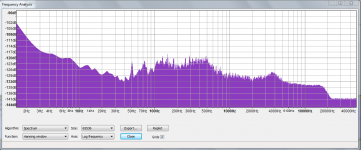
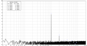
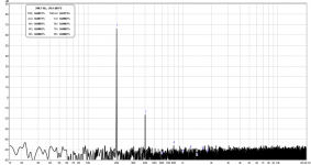
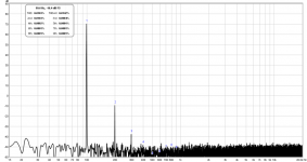
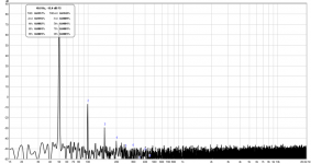
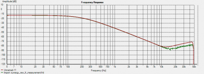
7th pic is the fr curve as REW sees it. The crud between 10Khz and 50Khz is what concerns me, and there does appear to be an abhoration at 30Khz.... I used to get this in holm on the breadboard, but it is much cleaner on the PCB.
8th pic is holm impulse measurement. I clicked the reverberation button in the impulse response. I don't understand what it is showing me but I suspect it is a clue! 300ms seems a long way into the impulse though...
edit: added nith pic, which is rew measurement exported and imported into holm impulse. Interesting that it looks a whole lot better in holm impulse than it does in REW. I'm starting to wonder more and more about my measurements and whether it's simply time to build the proper ones and have a listen (I can here James cheering 😉 )
So the moral of this story is I need to get some of the LM opamps, and I also need to work on my little project for making a balanced to single ended converter so I can get decent performance out of my focusrite 2i2 when testing single ended equipment!
Tony.
I've done Distortion tests tonight. Though they are not particularly valid, I think they show promise. My focusrite 2i2 has very good distortion performance when running in balanced mode. However the performance drops markedly when outputting balanced into a single ended load.
1st pic, focusrite in balanced loopback 1Khz.
2nd pic focusrite in unbalanced loopback 50Hz (yes I forgot to do one at 1Khz :rolleyes)
3rd pic synergy at 50Hz (note only marginally higher distortion than the focusrite unbalanced loopback). around 0.003 % more.
4th pic synergy 100Hz distortion
5th pic synergy 200Hz distortion
6th pic synergy 1Khz distortion (note that it is getting worse as we go up, but I think this is basically because there is less difference between the fundamental and the 2nd harmonic (ie the 2nd harmonic stays relatively constant but the fundamental is attenuated a lot more).
7th pic is the fr curve as REW sees it. The crud between 10Khz and 50Khz is what concerns me, and there does appear to be an abhoration at 30Khz.... I used to get this in holm on the breadboard, but it is much cleaner on the PCB.
8th pic is holm impulse measurement. I clicked the reverberation button in the impulse response. I don't understand what it is showing me but I suspect it is a clue! 300ms seems a long way into the impulse though...
edit: added nith pic, which is rew measurement exported and imported into holm impulse. Interesting that it looks a whole lot better in holm impulse than it does in REW. I'm starting to wonder more and more about my measurements and whether it's simply time to build the proper ones and have a listen (I can here James cheering 😉 )
So the moral of this story is I need to get some of the LM opamps, and I also need to work on my little project for making a balanced to single ended converter so I can get decent performance out of my focusrite 2i2 when testing single ended equipment!
Tony.
Attachments
-
 synergy_Low_pass.png46.1 KB · Views: 93
 -
 rew_fr_curve.png50.3 KB · Views: 98
 -
 synergy_1khz_distortion.png59.7 KB · Views: 101
 -
 synergy_200hz_distortion.png59.2 KB · Views: 174
 -
 synergy_100hz_distortion.png59.4 KB · Views: 178
 -
 synergy_50hz_distortion.png65.1 KB · Views: 265
 -
 focusrite_loopback_50hz_unbalanced.png62.1 KB · Views: 264
 -
 focusrite_1khz_distortion_balanced.png60.9 KB · Views: 288
 -
 synergy_Low_pass_compare.png25.8 KB · Views: 89
Last edited:
Tony,
Could you check with a picture of the signal just before the gate stopper of the output buffer to make sure the 30kHz problem does actually come from the FDNR and not some other source?
This has been a problem for quite awhile and nothing yet seems to point to the source of the problem so maybe another review of the circuit (re filter, etc) to make sure nothing has been missed.
Did Sy's original FDNR filter work the same way, and did he ever correct the error in the circuit? I don't remember anyone actually building a finished unit so maybe there was also a hidden problem in it too.
A bit outside the box, and not sure how to implement it but would there be any benefit in trying to operate these ICs in classA - (something about tying the outputs to a rail ...?)
Hi James I guess I could hook my scope probe up and test various points around the circuit. Not tonight though 😉 It's possible this 30KHZ thing is something inherent to the focusrite running in balanced to single ended mode. It may be a red herring.
SY never did a FDNR. He used a gyrator for the high pass, and a sallen key for the low pass. The FDNR in this application is entirely my own concoction 😉 Yes SY did build his, and he assures me it worked properly. The errors were in the calculations he put on his website (and no I don't think he has corrected them yet) 😀
The class A bit is getting totally beyond my expertise, I really am an ignorant trying to make something work that has no right to be 😛
I (believe it or not) am much much happier with this now than I was when it was on the breadboard. One thing that is good, the opamp and the fets are not even getting warm, so I don't think that there is an oscillation problem. It could be that once the opamp starts running out of steam the accuracy goes to pot and what we are seeing is low level distortion at around 60DB down. Something that in a bass application I'm hoping will be completely irrelevant. The noise, and distortion plots have actually encouraged me. They are not showing anything particularly untoward.
I'm actually very interested to see how the circuit performs for kinku's application (in the sim)... the low crossover frequency point is something I've felt was part of the issue, for a long time. I've just never got around to simming it at a higher frequency.
Tony.
Could you have a look in the SIM if adding maybe a series resistor to the '+' input of U8 will do anything positive?
It seems to be directly connected to whatever is happening on the signal line with just the R41 and cap as a filter
And, I'm probably 'talking thru my hat' as usual!
It seems to be directly connected to whatever is happening on the signal line with just the R41 and cap as a filter
And, I'm probably 'talking thru my hat' as usual!
I really appreciate your help Tony. The corner frequency should be 41.1KHz-20KHz = 21.1. Considering it is not easy to cut steeply down I can go down to 20Khz so that downward slop may start at 18khz. But the first image will appear at 21.1 kHz and a 60db attenuation is needed between 18 and 21.1 KHz . That is the challenge too.
Sorry, missed your last post - it mightn't look as tho you're making progress but each time a problem arises, you learn more about how these things operate and we all gain something - nobody in recent years has revisited these FDNR things apart from the experts and possibly some of the industry professionals - most everyone seems happy with the S-K solutions and/or series filters and it's not very often taht someone wants to try something like this.
I'll bet the high freq problem will be something simple that simply got overlooked ...
I'll bet the high freq problem will be something simple that simply got overlooked ...
- Status
- Not open for further replies.
- Home
- Source & Line
- Analog Line Level
- The Synergy "Active" Crossover