edit: just out of interest what frequency were you crossing over at? I've been wondering for a while whether there is a problem with lower crossover frequencies due to the opamp running out of bandwidth at higher frequencies...
I think it was in the 2-2.5 kHz range.
OK thanks (I'm using 300Hz). One of the things I always wondered about was that I saw these used as antialiasing filters in DACS (which are at a high frequency, > 20KHz). The designs were using opa2604's (which is what I originally tried to use). The 2604's had more of an issue with oscillation than the 2134's so I changed over to the 2134's...
I'm hopeful that what small problems I still have on the breadboard will be remedied by the tight pcb layout 🙂
Tony.
I'm hopeful that what small problems I still have on the breadboard will be remedied by the tight pcb layout 🙂
Tony.
I got the boards today 🙂 Quality is excellent for the price paid! it came to around $28 US with shipping for the 10 boards.
There is an issue, but it is my fault, not the board manufacturers. I was trying to work out how I managed to do this, as I thought I had checked the gerbers over and over to make sure everything was fine. Then I remembered that the day I zipped them up and sent them, I was off work sick. Me not wanting to waste the opportunity decided to finalize and order the boards... silly me!
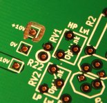
Basically I moved the +10V pin slightly and generated the gerbers again, I guess I didn't look at them before zipping them up and submitting. The problem is that KiCad doesn't automatically re-do filled zones when you move something, so the +10V is directly attached to the ground plane on one side of the pad 😱
Moral to the story is ALWAYS run a DRC before generating gerbers in Kicad. Second moral is no matter how small the change do check the gerbers again! Third moral if you aren't well enough to go to work, don't try and do something that requires dilligence!!
Anyway attached is a scan of the boards (and a screen shot from kicad showing the issue, which is quite obvious 🙄) , you will be able to see the problem. I'll need to use the dremel to cut a small trace around the pad. for each board, and then it should be fine. Hopefully that is the only issue!
I haven't ordered all the parts yet, was optimizing the filter slopes, I thought the boards would probably be another week yet!
Tony.
There is an issue, but it is my fault, not the board manufacturers. I was trying to work out how I managed to do this, as I thought I had checked the gerbers over and over to make sure everything was fine. Then I remembered that the day I zipped them up and sent them, I was off work sick. Me not wanting to waste the opportunity decided to finalize and order the boards... silly me!
Basically I moved the +10V pin slightly and generated the gerbers again, I guess I didn't look at them before zipping them up and submitting. The problem is that KiCad doesn't automatically re-do filled zones when you move something, so the +10V is directly attached to the ground plane on one side of the pad 😱
Moral to the story is ALWAYS run a DRC before generating gerbers in Kicad. Second moral is no matter how small the change do check the gerbers again! Third moral if you aren't well enough to go to work, don't try and do something that requires dilligence!!
Anyway attached is a scan of the boards (and a screen shot from kicad showing the issue, which is quite obvious 🙄) , you will be able to see the problem. I'll need to use the dremel to cut a small trace around the pad. for each board, and then it should be fine. Hopefully that is the only issue!
I haven't ordered all the parts yet, was optimizing the filter slopes, I thought the boards would probably be another week yet!
Tony.
Attachments

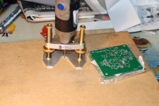
OK I've fixed the +10V issue 🙂 1/32nd router bit in my dremel with my stewmac router base did the trick. It's not as nice as a properly etched groove but it will do the job 🙂 all ten boards are fixed. The first one is a bit dodgy, I tried setting the depth on a piece of coated mdf but it was way off. It can be the experminenter board 😉
Hopefully no more "fixes".
Tony.
Hopefully no more "fixes".
Tony.
Attachments
Ah Tony, a minor problem and an easy fix - it'll be great if that's the only drama we get. The boards look to have quite a bit of useful spare room on them for any sort of mods
Incidentally, I have a couple of extra Salas Shunt Regs pcbs here (the BIB version - the higher current one) if you want to try them in comparison to your YARPS regulators
Where did you get that stand for the Dremel? It looks really useful. I got a rather neat press for the pcb drill from china (the only reasonably priced one that I could find) but that one of yours looks ideal for the larger Dremel type drills, especially if it's an adjustable fit.
Hi James, I got the router base here --> STEWMAC.COM : Precision Router Base
It's very nicely made. One thing that disapointed a bit is that it is not really able to be used (I don't think) as a plunge router. I was hoping I may be able to use it as a drill press (may still be able to using the depth screw but haven't tried.
I actually bought it for removing copper from pcboards. I just hadn't got around to doing that (non-etched) board yet 🙂
I'll pass on the shunt regs for now. I don't think I have the room for them! I'm not sure if I'd hear the difference anyway.. somewhat tin ears here 🙂
Tony.
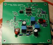
Making some progress. calling it a night. The board stuffing is going ok, no problems. Though one thing I have noticed is that changing out the opamps might be a bit tricky due to the closeness of the big caps. won't be impossible but tricky.
The SMD soldering leaves a bit to be desired, but for a first time I guess it is ok.
This is a quick and dirty one for making sure everything is ok.. just jaycar resistors and caps (though I had a few spare 1837's so have used those in the problematic low pass section). The final versions will probably get elna silmic II caps and prp resistors (except for a few which will probably be vishay's depending on how anal I want to get about accuracy between channels... the vishays would be 0.1%)
Note that RN60D's don't actually fit for the majority of the resistor positions... I had some and tried one and it is a little too long. They would need slighly bent under leads to fit. The PRP's fit just fine 🙂
Tony.
Attachments
Last edited:
Just put those electrolytics on the underneath, on their sides, so easy to solder the wires - just need slightly higher standoff - looking good so far - what sort of resistors are they?
Hi James, the solder is actually wicking through the plated through holes well. No need for soldering on the top side of the board as far as I can tell so far. I should probably have a look at the ground connections of some of the resistors with the loupe to be sure.
They are just plain old metal film resistors from jaycar at the moment. Had to piggyback two 10 ohm ones to get the 5 ohms I needed for one position. I might hook up the low pass before I finish the rest to try it out, since it has been the bugbear.
I've also realized that there is another omission
 I didn't put in a 220K resistor to ground on the input... 😱 easy enough to solder one across the input terminals on the back of the board though.
Tony.
They are just plain old metal film resistors from jaycar at the moment. Had to piggyback two 10 ohm ones to get the 5 ohms I needed for one position. I might hook up the low pass before I finish the rest to try it out, since it has been the bugbear.
I've also realized that there is another omission
Tony.
Looking good, but i see what you mean by the Vishay caps. Are they the 1%PP film? I'm also using that type and the 5x7mm size make things tight on the 50mm constraint. Ive also got the 8x11mm 0.1uF to fit in...
Yes they are the vishay MKP1837's 1% types and they are mostly the 100nF ones. They fit ok but it doesn't leave much manouvering room for getting at the opamp socket! James idea of mounting on the reverse side would solve the problem though if it proves problematic 🙂
Another annoyance has been that when simin a 3rd order high pass I need a 150nF cap for the second one and the MKP1837's only go up to 100nF... Will need to look at something else (probably a panasonic) for that one, unless I can tweak the values to get down to 100nF for that position.
Tony.
Another annoyance has been that when simin a 3rd order high pass I need a 150nF cap for the second one and the MKP1837's only go up to 100nF... Will need to look at something else (probably a panasonic) for that one, unless I can tweak the values to get down to 100nF for that position.
Tony.
I'm forever adding 'things' to the bottom surface - I figure that as we use a double sided tracks, why not use double sided components, particularly if they're lower profile than the standoffs - can just // up another cap (to the 100nF) underneath to required 150nF value
Tony, those Jaycar resistors aren't very good 'sound' - noticeably 'hard' and 'thin', and particularly as gate stoppers - can send up some Phillips PR1s, or perhaps Beyschlaggs, have some PRPs and TRWs for the 'stoppers' - no Rhodestein 'resista' left anymore
Perhaps a later mod if all goes well - sorry, when, not if!
ps: I think WES keep a good range of good quality resistors, too - not sure how convenient ...
Hi James, was just a case of want to get something going to verify that the oscillation problem is either fixed or still present. Was planning on putting an order in to partsconnexion to get the prp's that I am missing (I actually have all of the 220's and I think 220K's) Will get some silmic II's as well (and some mills resistors for my crossover while I'm at it).
I didn't want to put in the order for nice parts if it turns out I have to go back to basics! I've already done that once (hence why I have some of the prp's but not all). This first build is just going to use the textbook 2nd order 200Hz that I originally breadboarded (which is not what I will use in the final config) so that I can verify whether or not the PCB has fixed the issue I had on the breadboard.
If it does I will send out the boards 🙂 It will probably be a little while before I build the final circuit. Need to do some experimenting with one channel, measure the results and once happy I will order the final components and make the two channels.
Piggybacking a 47nF mkp1837 on the reverse side of the board with a 100nF on the top is a good solution, which would allow up to 200nF easily, I think I will go with that option, thanks! I might order a few extra values in the 1837's just so I have some options.
I checked element14 on the weekend, and the 1837's ranged in price from 34c to $13 each (depending on value)... today the prices are different again... weird..
No problems - early days yet.
Not sure about Element14, but you might check their GB site prices -sometimes ridiculously different (maybe worth a phone call to the Sydney office too)
I've got hundreds of the 15nF ones if any use to you.
Suggest you have a look at "Handmade Electronics" in the US for the PRP, etc resistors,Silmics - hell of a lot cheaper, no crazy surcharge, and good guys to deal with. Unfortunately, I can't get the Rhopoints and Neohms from them ...
Yep those 100nF 1% are large. Ive got smaller sized 1uF 5% PP caps, but i figured 1% was necessary for stability of the crossover points, as i suspect you do also, otherwise id have used the normal slim film caps.
Thanks James, I've not used them before.
mondo yes I went with the 1%'s for close tolerance. Not so much for overall accuracy in the slopes but more for matching left to right.
Tony.
mondo yes I went with the 1%'s for close tolerance. Not so much for overall accuracy in the slopes but more for matching left to right.
Tony.
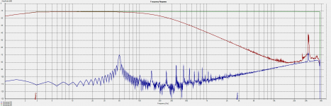
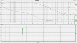
Well, I've fired up the low pass, stuck it on holm impulse, and I have to say I'm disapointed 🙁
It actually looks worse than the last breadboard implementation...
I don't know where the spike at around 32Khz is coming from. It could be noise that is being picked up, because if I do a record in holm with the input floating (ie just connected to my adaptor box) it shows a similar (though not quite as big) spike in the FR.
It could be that I am seeing noise that is burried normally showing up where the signal is attenuated sufficiently.
Anyway attached graph has green loopback of my focusrite 2i2 unbalanced. red is the synergy as built on the new pcb for the same freq (textbook 200Hz) as the breadboard circuit.
Blue is with the synergy disconnected completely... just the output lead off the focusrite dangling and the input lead dangling. This gives me some hope that the 32Khz spike is at least not something inherent to the circuit 🙂
Tony.
Attachments
OK I had a break and came back and tried measuring a bit differently. I moved the focusrite onto the floor, and I plugged direct from the output to the synergy into my balanced in (without my normal little SE to balanced converter box (basically just a set of rca's and jack plugs wired with ring and sleeve to the earth of the rca and tip to the live of the rca).
Well it isn't 100% noise free, but it is close enough for me to put what is left down to measurement problems 🙂
I think we have a viable FDNR low pass filter 🙂 It will probably be a little while before I get something going that I can get speakers attached to but I'm feeling much happier about this now!
There are some glitches in the impulse response, and in the phase (note that the phase does go wacky in the sim as well, but only goes up to about +60 deg so I'm a little suspicious of the phase as measured by Holm)
Attachments
I'm no expert, but wouldn't it be better to do that test again with the signal input grounded, rather than floating?
EDIT: you beat me to posting, so perhaps my post is now meaningless 😉
EDIT: you beat me to posting, so perhaps my post is now meaningless 😉
Last edited:
Hmmm I could measure the noise floor I guess with input grounded. The test above is actually a swept sine test so need the input to get the effect of the filter on the output 🙂
I'm going to try some other tests. I might see what REW comes up with 🙂
I'm going to try some other tests. I might see what REW comes up with 🙂
- Status
- Not open for further replies.
- Home
- Source & Line
- Analog Line Level
- The Synergy "Active" Crossover