Hey wait! Don't you need 5 channels to go with your 5 Iron????
I have to get the noise out of the 5 Iron. I put that on the back burner, work has been brutally busy this year, so my bench time has dwindled way down. I may end up with a 2 Iron, because I replaced my low frequency amps with high power / high gain amps.
Also on the agenda: get a distortion analyzer rig set up. I have the parts, but haven't had the time.
The good news is that my "winter break" starts mid next week, so I should get some bench time.
Excellent that you're going to have a bit more DIY time. I just now got back into the DIY groove a bit after a busy year also.
Side note: I got to visit Cleveland for the first time in September. Checked off a bucket-list item and went to the Rock and Roll Hall of Fame. 🙂
Back to the topic...
WARNING - ABSURD learning question below. For those that are squeamish, read no further.
I've got a number of options for consideration. I may take a "staged approach" to this build. One stage 'could' be... a lower rail voltage. Much lower.
I've read the articles, read the threads, watched the videos, looked at Lynn's and Woofertester's curve traces, and reviewed and reviewed ZM's distortion FFTs.
Something is not clicking, and it's tied to a lack of knowledge (yet again) re: a first principle that I can't wrap my brain around. i.e. the choice of operating point for a device within its rated criteria.
One of the wonderments of Papa's designs, ZM's designs and many others is intentionally altering the distortion profiles of amps. I first thought about this before ever getting into DIY having read the "Bob Carver Amp Challenge" many years ago. It captivated me. I also keep Bob Cordell's (loosely quoted) statement that amps sound differently b/c of the ways they misbehave close to mind.
Either way... onto the point. I can't find why ~+60VDC was chosen for the rail. I saw ZM's plots where eking higher resulted in less than ideal results. However, I didn't see anything lower.
Is that b/c the parts / circuit are not designed for that? Is it b/c we 'all' want MORE POWER? Is it b/c that's the sweet spot for the devices?
tl;dr - I am wondering if I can run a ~+50V rail. It's mainly a thought exercise, but it is spurred by having parts immediately available to try a proof-of-concept. I am definitely going to build a new/proper PSU designed for this amp, but it could be interesting as long as nothing goes kaboom (unlikely), or if it just won't work properly.
Thanks for indulging the silliness. 🙂 I hope in the best case it provokes some thought or at worst a good laugh. I never mind looking silly if I learn a bit.
Sure, you can run at lower voltage, and different current. The question is what will the distortion profile look like?
Simulations can give you an idea, and testing with the built amplifier will give you definitive answers. Using a distortion test rig, you can measure while varying the Vds and Iq of the output device and choose your preferred operating point.
More diy fun.
Simulations can give you an idea, and testing with the built amplifier will give you definitive answers. Using a distortion test rig, you can measure while varying the Vds and Iq of the output device and choose your preferred operating point.
More diy fun.
I’m guessing it was part of the decision to target 50W output, but am curious to hear what ZM says.
pretty much lowest possible voltage to start getting any decent THD figure from elevator controller Tokin SITs
as always, loading (speaker impedance dominating there) issue
same as any active device - U-I graphs can tell you all , see any triode loading lines tutorial and everything should be crystal clear
if you're just thinking about SissySIT, as opposite example (of lower rail per part) - parts are used in source follower arrangement, completely another context
That’s cool. So the higher overall output (compared to most around here) is really just a by-product of getting to a lower thd?
sorta first goal, then product
if you're willing to go to 90V, THD should go down, and power would be factor of dissipation you can allow
if you're willing to go to 90V, THD should go down, and power would be factor of dissipation you can allow
Hey ItsAllInMyHead,
Uncle Mike's L'amp article has a lot of discussion on load lines:
http://blog.audiomaker.tech/pdf/lamp part one.pdf
Dennis
Uncle Mike's L'amp article has a lot of discussion on load lines:
http://blog.audiomaker.tech/pdf/lamp part one.pdf
Dennis
Thank you all so much!
Dennis, that's exactly the type of information I was looking for re: load lines. That's the fundamental principle that I'm still not 'there' on. Even with Lynn's plots, my mind goes to pieces. 🙂 With time. With time.
ZM - I obviously misinterpreted one (or many) of your THD FFTs and posts. I thought the charts "screaming" with the THF-51S were showing that going higher with the V+ started to cause the higher distortion. Also, as always, you are a mind reader. Yes, I was thinking of SissySIT. 🙂
 to all.
Edited to add - Thanks to Ben, too. That darn Canadian flag and fast reading had me overlap both yours and Dennis' posts.
Now to finalize my parts list for the PSU.
Dennis, that's exactly the type of information I was looking for re: load lines. That's the fundamental principle that I'm still not 'there' on. Even with Lynn's plots, my mind goes to pieces. 🙂 With time. With time.
ZM - I obviously misinterpreted one (or many) of your THD FFTs and posts. I thought the charts "screaming" with the THF-51S were showing that going higher with the V+ started to cause the higher distortion. Also, as always, you are a mind reader. Yes, I was thinking of SissySIT. 🙂
to all.Edited to add - Thanks to Ben, too. That darn Canadian flag and fast reading had me overlap both yours and Dennis' posts.
Now to finalize my parts list for the PSU.
Last edited:
Dennis, I just did my 3rd pass through "Uncle Mike's" article. I had never found it prior. It may be the single most informative piece I've read in my time DIYing. It ties together so many principles that the advanced DIYer may just know from rote and makes them accessible to a person such as myself. Absolutely fantastic stuff! Yes, I printed out some graphs and needed the straight edge to visualize the rotation around a chosen operating point. Just the very simple principle of the "distance between the lines" showing variable gain at different loads was a light bulb moment. I can now say, I understand the principle.
I've learned just enough basic DC and AC electronics from text books and such (at a primary school level) over the past year, and I admittedly just barely understand the fundamentals of N and P devices and 'depletion mode'. This article took me to a new level of grasping a bit more about tying things together.
For others out there that are visual / hands-on learners, this is required reading. A bit down the road, I'll be anxious to try things out with some devices I don't care about potentially smoking. I want to see if I can rig up something similar to what he did with his scope. I am pretty sure I can do X-Y plots and export. New thing to try. Currently my test supplies would not be remotely sufficient.
Last edited:
I’m definitely in the same boat with you. Sometimes I think I’m getting it, and then I read something that reminds I don’t get it at all. Nonetheless, I do enjoy learning about what makes these things work.
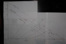
I found a set of curves for the THF-51S here:
Tokin SIT low voltage high current curves
And they were traced using ItsAllInMyHead's THF-51Ss.
So I did some drawing on the curves. Assuming that my knowledge of load lines is correct, I did the following:
Since the amplifier is CCS loaded, the static load line is horizontal and equal to the CCS current. For the dynamic load line, I assumed the CCS has infinite AC impedance, which in parallel with the speaker 8 Ohms, gives an overall impedance of 8 Ohms. From that I drew the dynamic load lines for 60V/2.3A and 50V/2.0A. The slope of the lines is the effective load impedance, 8 Ohms.
I then drew the dynamic load lines for Vds=35V Iq=2.3A (original operating point), which has the same slope (same effective impedance) and for Vds=28V Iq=2.0A (new lower operating point). I arbitrarily chose this operating point, keeping in mind not to have Vds exceed 0.50 x 50V by too much so that clipping not too asymmetrical.
The goal is to choose an operating point where equal changes in Vgs positive and negative gives equal changes in Vds. Looking at the chart the best operating points would be where the load lines are straight and parallel.
So looking at what I plotted, it doesn't look too bad to me. The maximum output power is lower but that is to be expected. The distortion at higher output levels will probably be higher too. Perhaps a lower Vds and higher Iq might be better.
So my thought is that if ItsAllInMyHead already has the power supply parts, why not experiment. It would be educational.
Just for kicks, I also did some simulations and the results looked decent. But of course simulations are not the real thing and so much is dependent on the accuracy of the THF-51S model. Having said that, my 1W sim gave good results.
Again, this is not meant to disrespect Zen Mod, but for me to try to learn more about amplifier design. I know so little.
I hope what I have shown is not incorrect.
Attachments
more knowledge, more logical thinking, more knowledge
understandig of graphs precedes LTSpice, which one can use without actually knowing physical processes
and, after graph fun, one can proceed with sims, or jump ditto to actual prototyping
actual prototyping will always reveal what we can't see ( or still can't see and understand) in graphs ....... and in case of SB (from actual protos on bench) we can clearly see that Uds is dominant over Iq in decreasing THD, with clear decrease in THD with higher Uds
which is confirmed with few specimens of each type ...... an I even didn't documented values for Uds<30V ...... really nothing to document
and - no reason at all that I'm even thinking of disrespect...... truth and learning always were way above my own ego, and we all well know that ZM is still and shall stay Master of Dumbness
Ben, It seems we walked similar paths, but with me trailing soooooooooooooo far behind in understanding.
The first thing I did after reading Mark's wonderful blog was to go back yet again and revisit the plots that Woofertester created. I wanted to see if I could make any sense of it all. He did all the work, and I haven't put it to use yet. Admittedly, I did not get quite as far as you. 🙂 I truly appreciate your post. It helped tremendously. It confirmed a few things, gave me some new thoughts, and showed me a few errors in my thinking.
Simply understanding a constant current source... one step. I am still absorbing your comments. Now, I feel like I have the 'answer in the back of the book'. However, I am still not 'there'.
FWIW - The devices that Woofertester measured will go into the Singing Bush. The other pair is still dedicated to the SissySIT.
More to learn tomorrow. Now, my brain is toast and needs to relax with some tunes and maybe, just perhaps, a well-earned beverage.
I also need to publicly thank Botte for allowing me to run some thoughts by him and his indulgences with my walls of text.
I should just change my signature to say... "Thanks to you all!"
I'll close with a recent ZM quote.
"just imagine how big my joy is, whenever I think that I figured out something... joy episodes is what counts"
Well said, sir.
Here is something on CCS and load lines:
CCS’s and Loadlines – wauwatosa tube factory
It is tube based but the principles still apply.
CCS’s and Loadlines – wauwatosa tube factory
It is tube based but the principles still apply.
Thank you, Ben!
I love his writing style. 🙂 I'll have to read this one a few more times also to let it all sink in.
I love his writing style. 🙂 I'll have to read this one a few more times also to let it all sink in.
I'm about to start on soldering PCB's. I printed a checksheet for installing parts. I printed ZM's Tips/Tricks startup procedure.
One thing jumped out at me... I'm planning to use one Antek AN-5450 per channel into a CLC PSU. The SIT / Gain PCB needs 15V bias supply. Antek has extra 12 and 18V secondaries. Can I use one of those instead of 15V's, or do I need a 15V donut? Any adjustments required - R15, R16 or other?
Also for R9, why the socket? Is it to change out R9? Or is to have the leads high enough to clip onto for measurement? Can I just install the resistor high enough off the board to make it easy to clip to?
- Home
- Amplifiers
- Pass Labs
- The Singing Bush