As usual I had the direction of the needed value in the wrong direction.
Paralleling with a 33K across R1 and I am close enough to where the other amps are.
Working on the kitchen table with line voltages slightly lower than what comes out of the isolation transformer and I am just under 36.4 at 460 mV - it will be where the others are when moved into position.
Whether it makes any sonic difference I have yet to hear but one less thing to think about while listening.
Thanks to ZM, Cody and asphalt.
A couple volts less in the power rail is of little consequence as far as perceived power is concerned. Of more importance is whether the transformer is able to maintain good regulation under load. A transformer with 48V secondaries may be a better choice if it supports higher current under load.
The Singing Bush calls for a 450VA to 600VA transformer per channel, depending on voltage and quality.
The Singing Bush calls for a 450VA to 600VA transformer per channel, depending on voltage and quality.
In position - 36.5 Vds 3.77 Vgs 460 mV
Finding a 6,58K resistor is, of course, im[possible,
I assume going for a lower value is fine.
Finding a 6,58K resistor is, of course, im[possible,
I assume going for a lower value is fine.
I am using a 400 VA transformer for the below 500 Hz part of the speaker and a 300 VA for the tweeter.
When I started this 300 VA was said to be sufficient.
When I started this 300 VA was said to be sufficient.
'twas double borderline case;
SIT calling for borderline negative Ugs
MOS calling for borderline positive Ugs
SIT calling for borderline negative Ugs
MOS calling for borderline positive Ugs
The amp sounds good but the obsessive in me wonders if
I should try another SIT?
Both of the original pair I received have "problems". Still waiting for the replacement to arrive.
I got the chance to remove the cable from the buzzer and soldered in a short with no change in the noise.
Thanks,
I should try another SIT?
Both of the original pair I received have "problems". Still waiting for the replacement to arrive.
I got the chance to remove the cable from the buzzer and soldered in a short with no change in the noise.
Thanks,
Meant to ask what brand of resistor do you use in the kits?
Might as well stick with the same.
Thanks, again,
Might as well stick with the same.
Thanks, again,
'twas double borderline case;
SIT calling for borderline negative Ugs
MOS calling for borderline positive Ugs
just a matter of biasing/control voltages
not having anything with actual performance/sound of amp itself
so that amp, if set to prescribed values, is not problematic in any way or manner
for buzzer amp - when you change SIT, you'll know more ......... if you checked everything else thoroughly, that's sole thing left to check
resistors - normal variety/standard industry quality of 0207 metal films (Vishay, Yageo,Pana,TEC etc.)
biguns - standard industry quality 3W MOX
personally - I'm not looking for better ones, nor I think that changing any for more expensive ones will lead to better sound
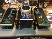
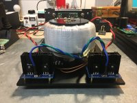
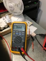
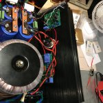
Moving along with my SB-SIT amplifier, finished the power supply today, no load is 66VDC. Dim bulb tester was used during the first tests, no issues, I'm using Mark Johnson's soft start board, works great so far.
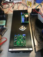
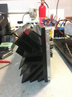
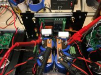
The heat sinks are drilled and tapped with the PCB's and SIT installed, finished the wiring of the boards and I'm ready to start the biasing procedure.
First some pics:
The heat sinks are drilled and tapped with the PCB's and SIT installed, finished the wiring of the boards and I'm ready to start the biasing procedure.
First some pics:
Attachments

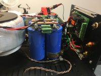

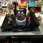
Last of the pics, first of the dumb questions:
1 - Do I need to have the speaker outputs connected with the 470 ohm resistor during the bias procedure?
2 - Should the inputs be shorted?
I have to connect the 15vac wires to the upper PCB and then the inline fuse (3A slo-blo) on the 60v rail and then I should be ready unless someone sees another mistake I made.
Attachments

1. Yes
2. Yes
ZM's start up procedure:Singing Bush Start-up Procedure
Set trimmers as ZM's instructions.
Start up only one channel and finish before starting the other channel. Also note that each channel start up is in two stages. Note that one wire connecting the two boards (actually it is the wire connecting the Mosfet board to SIT drain) is not connected for the first stage of start-up for each channel.
Do not power up the second channel when setting up the first channel.
Last edited:
And definitely make sure that 15vac is connected throughout the whole setup. Gotta keep that SIT throttled back 🙂
From what I have assumed the 470R is to bleed the output cap.
I have measured with caps and resistor in place and without either and saw no difference.
Same with shorted input even though I do not doubt it is good practice.
I have measured with caps and resistor in place and without either and saw no difference.
Same with shorted input even though I do not doubt it is good practice.
Next dumb question, on the upper/mu PCB, there is a spot on the PCB for C*,C** referred to in the schematic. It is marked as additional solid cap, motor run?
I don't have room for a large motor run cap, what value and type could I use instead?
Or is it not needed?
I don't have room for a large motor run cap, what value and type could I use instead?
Or is it not needed?
there is enough place for small caps on pcb already
motor run is cherry on top........ and you can use these pads for separate smaller cap, if you want to put separate speaker posts at back and biwire to your tweets
motor run is cherry on top........ and you can use these pads for separate smaller cap, if you want to put separate speaker posts at back and biwire to your tweets
- Home
- Amplifiers
- Pass Labs
- The Singing Bush Tips 'n' Tricks