It will just drive the whole available current from its CCS to ground through its output MOSFET. 9V*0.5A=4.5W and if its heatsink is enough it can handle it for everHi Salas,
I am testing a BIB board to power a DAC, setup to output 9v ~500ma. The regulator board will be in a separate enclosure so i plan to run two wires between them, and just jumper the sense wires locally on the PCB. Question is, how will regulator board react if the dac cable is suddenly disconnected and there is no load, will it handle this scenario ok or will that cause issues?
Cheers,
Mark
That should work just fine as it will be mounted in a finned enclosure. It will probably never happen, but better to be safe than sorry.
I finally got the two SSHV2 boards up and running, but never figured out 100% what was causing my issues. I have a suspicion it was to do with the screw terminal blocks supplied with the kit making a dodgy connection between the outputs and sense wires. They have been working perfectly for over a month now.
Thanks again for the help!
Its always better to solder them wires when for permanent. The connectors are there mainly for testing simplicity.
They have been working perfectly for over a month now.
Thanks again for the help!
You are welcome, I hope they contributed an audible difference to your gear.
You are welcome, I hope they contributed an audible difference to your gear.
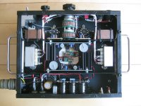
They really work great, rock stable, and perfectly quiet. I even came up with a novel mounting arrangement so i could mount two of them, and the constant current source plate loads onto the same heatsink 😉
Attachments
Hi
I have a question that might have been answered elsewhere, so excuse me if it was, but I did not find it. I built the shunt regulator to replace a simple 317/337 power supply in a professional mastering grade stereo equalizer. The electronics in that EQ are build on 4 circuit boards, two for the eq circuit and two for the in/out buffer. Each board has 22 Ohm resistors with 220uF caps on the power rails for decoupling. How should I handle that, since those resistors with the caps somehow counteract the advantages of the shunt regulator?
And where does it make sense to put the sense wires 🙂
I installed the board already and we are hearing some improvement, better transients and more air, even though the resistors/ caps are still in place and I jumpered the sense wires on the board. Could I try to bridge the resistors and remove the caps? And would it make sense to lead sense wires to all the four boards? Where should my star ground be? On the + or - board? Or close to the signal input in the case, right now it is in the case, I wanted to keep the LED and relays currents away from the precious signal ground.
Loads of questions, thanks for help.
T.
Hi Hop.sing,
Would you put up a schematic or a clear detail picture ,You will get some help then!
Happy listening!
NS
Would you put up a schematic or a clear detail picture ,You will get some help then!
Happy listening!
NS
Thanks for your answer. The item in question is already in use again and I did take no pictures, unfortunately.
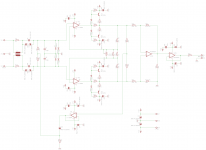
But I attached a little eagle sketch how the power input on the boards look like... I hope that helps a bit. The Opamps in the device ( A Sontec 250 EQ clone by the way) are opa2604s which are locally decoupled of course.
The four circuit boards are situated pretty close to each other, the longest cable run from the power supply would be around 10cm.
Thanks
Attachments

Those are typical RC noise filters so the 220uF capacitor's characteristics dominate after charged in 5ms. If they don't perform some mandatory local decoupling role too, its worth testing to remove the capacitors and use their empty pads as force and sense wires destinations. Try that, listen, and if all is working good and stable, even possibly better, keep the new arrangement. Remove the capacitors carefully so to can fit them back and revert to now configuration if its not a successful test. Good luck and let us know
P.S.
You can do two phase test. First remove the capacitors and bridge the resistors without employing the sense wiring. Listen. If encouraging, then its time to do the sense wiring test. Make "star ground" style bridging of each +/0/- from individual boards into central receiving branch nodes for the PSU's force and sense. Its complicated wiring for defeating 10cm of non sensed wiring but its the only way to evaluate it in your build. On the other hand, thick normal wiring can be close to that result due to short proximity. But you should experience the possible differences and decide if in the mood to do all those things.
Why 47r across the input inductor?
Why R34?
Would a limiting resistor in series with the 10VR27 prevent excessive gain when set to 0r0?
Why R34?
Would a limiting resistor in series with the 10VR27 prevent excessive gain when set to 0r0?
Why 47r across the input inductor?
This is either common mode choke or limiting resistor or two wire links. Whatever works best.
Why R34?
Probably unnecessary. Used it together with a coupling C in my previous design as another first order filter for bandwidth limiting.
R23,R24=1 ohm? Why?
To keep the other feedback resistors low in value to increase noise performance. That's what the discrete buffers are there for - to drive those low resistance.
Lotsa gain.
It's a mistake by itself, since it reduces bandwidth (and degrades precision) unneccessarily, but if considered as a goal, why not implemented with 10 times higher resistors? Small value resistors usually have a not negligible inductance (plus track inductance). 20 nH and 0.5 ohm forms a 4 MHz low pass filter. OK, I know BW is already limited to 50 kHz, but could have been much better if gain of first stage would be much lower, second stage would be higher, and IC8 were in the place of IC7A (where it was stable).
60 dB gain in 1 stage is never the optimal choice.
Why C45 is in the common mode feedback path?
And those transistors are totally useless if reasonable feedback resistor values are chosen.
BTW:
What is the purpose of this and why in this topic?
To keep the other feedback resistors low in value to increase noise performance. That's what the discrete buffers are there for - to drive those low resistance.
Not feedback resistor determines noise performance, but input resistance. (On both inputs.) If R9=47 (and probably much higher input generator impedance) is acceptable, then R23=10...47 ohms can not be a problem.
BTW: OPA1632 can be a much simpler and better solution. Cheaper also.
Because he has been trying to devise a reasonable low-noise amplifier setup for measuring various regulator designs.BTW:
What is the purpose of this and why in this topic?
1632 will be limited by the thermal noise of the input resistors. It's not a bad part, though, to follow a pair of input devices. Ironically I am expecting a UPS delivery that includes some of them on this very day.BTW: OPA1632 can be a much simpler and better solution. Cheaper also.
I do agree with you, though, that trying to realize all of that gain in one composite stage is somewhat ill-advised.
1632 will be limited by the thermal noise of the input resistors. It's not a bad part, though, to follow a pair of input devices. Ironically I am expecting a UPS delivery that includes some of them on this very day.
I do agree with you, though, that trying to realize all of that gain in one composite stage is somewhat ill-advised.
🙂
If source impedance is low, then input resistor can also be low. If source impedance is high, then noise is high already. But I see your point...
Maybe the best solution is a transformer with input capacitors. For example 200 turns primary (RDC=2 ohm), 1000 turns secondary (50 ohm) on an AL=10000). With 100 ohm input impedance it can work from 10 Hz to 20 kHz.
Last edited:
- Status
- Not open for further replies.
- Home
- Amplifiers
- Power Supplies
- The simplistic Salas low voltage shunt regulator