Its for 3.3V to 7V 0.6A CCS max and needs 9VAC 30VA Tx or 10V DCIN ready rail. That's the rough spec. Can cover from SUBU to Buffalo main feed for current in other words.
Hi!
On the original schematic, there is a 220 uF capacitor. What does this do?
In the Reflektor, no. Maybe 220R gate resistors? If talking about another type of my reg projects please link.
Hi Salas,
In the Reflektor-D build guide, you've recommended Cm value to be between 10000-22000uF. What are the benefits of using such high capacitance? (I've built a few Reflektor using 2 x 1500uF as Cm, and I'm wondering if I should change them to 2 x 6800uF).
If I use 2 Reflektors to give a dual-rail supply, each with 22000uF, do I need to start worry about inrush current and add a NTC before the transformer primary.
Thanks and regards.
100Hz rectification ripple smoothing is the benefit. With 10000uF and 400mA CCS I got 380mV pk-pk across CM (135mV RMS) and NOTHING when scoping for 100Hz or any other frequency on the output. So the regulator filters ripple excellently but better not make it overwork about it. Hence the allowance for big capacitor on the official board. Good quality 10000uF 25V should be the base choice.Hi Salas,
In the Reflektor-D build guide, you've recommended Cm value to be between 10000-22000uF. What are the benefits of using such high capacitance? (I've built a few Reflektor using 2 x 1500uF as Cm, and I'm wondering if I should change them to 2 x 6800uF).
If I use 2 Reflektors to give a dual-rail supply, each with 22000uF, do I need to start worry about inrush current and add a NTC before the transformer primary.
Thanks and regards.
Hi Salas.
You wrote that maximum V is about 7V. Could it be forced to 8V without risk? What changes needs to be done in that case? I recon it might be possible?
Regards
You wrote that maximum V is about 7V. Could it be forced to 8V without risk? What changes needs to be done in that case? I recon it might be possible?
Regards
There are three LEDS positions in the final PCB. Two dedicated and one extra in the Rx/J/D area. One way is to bodge 1N4148 diode in the cathode pin of the third one while picking highish Vf greens too. It will also do better with 12VAC trafo when going 8V out. The CCS set and sinks dissipation should be checked with a dummy load representing the actual target project's current max draw. R(dummy)=Vout(8V)/maxDraw(project).
@Turbon
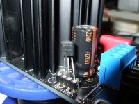
I performed an experiment on how to reduce the components count for your 8V inquiry.
I tried an LM329DZ precision reference with low noise and low impedance characteristics. Not one was spot on 6.9V nominal out of five that I had in a bag.
They gave 7.1-7.15V (still within factory spec). Using jumpers on LED1 and Rx/J, I inserted the LM in LED2 position but with its cathode looking towards the sink.
Its to be applied like a Zener. First LM leg from the left in the picture hangs on air, as it makes no contact to the chip inside it may be spared when having two pads only.
It worked fine, but It produced 8.31V output. I don't know if that is acceptable in your application. You will surely need a 12VAC Trafo also.
Attachments
- Status
- Not open for further replies.
- Home
- Amplifiers
- Power Supplies
- The simplistic Salas low voltage shunt regulator