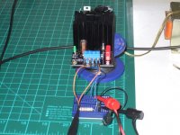
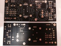
My virus scan just healed
roboot64.exe
about 2hours after looking at photoshop !
Microsoft Essentials Anti-Virus says nothing is wrong after I asked it to scan the pictures. Here they are attached.
Attachments
Digikey has 8,705 2SK880BL in stock. Use higher RR degeneration for 2mA CCS and its the same thing.
Thanks Salas,
Was scouring the net for the GR...with no luck.
Digikey BL is great news.... they even have GRs ...a few,why did my googling not show them and why oh why did i not think of looking there first ?😡🙁
😀
I'm finishing my SDTRANS SD reader and DAC and this comes at exactly the right time for the power supply box.
....and not forgetting the most important...THANK YOU for providing the means for my DIY to sound so much better !!!
I'll pay you a beer next time I'm in Athens, would be an honour,....in one of those nice Glyfada seaside places.
Last edited:
There are very positive independent subjective views about the Reflktor-D powering various DACs but I will not go into that, I have listened to it powering a SUBU3 in a big system with Beyond the Ariel style horn speakers and I can only say its alright, no problems. Its a decent candidate in other words.Thanks Salas,
I'm finishing my SDTRANS SD reader and DAC and this comes at exactly the right time for the power supply box.
....and not forgetting the most important...THANK YOU for providing the means for my DIY to sound so much better !!!
I'll pay you a beer next time I'm in Athens, would be an honour,....in one of those nice Glyfada seaside places.
You are welcome. What other stuff by my design have you used in your systems, please remind me?
...you are so modest 😀.
My test setup has been playing for some months with the BIB and sounding Great.
My test setup has been playing for some months with the BIB and sounding Great.
4-5.5mA for 82 Ohm RR
What do you mean JFETs around the current mirror? There are only BJTs there. Low noise PNPs. Use medium to high HFE 10% tolerance.
I was talking about the two fets that are in series with the Vfred diodes(and in paralel with two of the bjts of the current mirror)
Thx salas
Hi Salas,
The initial Reflektor has a RC zobel in parallel with C2, which no longer exist in your latest Reflektor-D from post 6495. Sonically, is it better not to have it?
Thanks.
The initial Reflektor has a RC zobel in parallel with C2, which no longer exist in your latest Reflektor-D from post 6495. Sonically, is it better not to have it?
Thanks.
Its a different MOSFETS and higher voltage level realization for different purposes. That Zobel is to help the big filter cap and it can be audible when powering wide bandwidth analogue circuits. Matter of preference regarding the tone of the filter capacitor. Not a main circuit function section.
I want to power PCM1704 DACs, could you post or link to Reflector-D schematic?
Or do you think is better to use BiB?
TIA
Or do you think is better to use BiB?
TIA
I want to power PCM1704 DACs, could you post or link to Reflector-D schematic?
Or do you think is better to use BiB?
TIA
Post #6495
The Reflektor-D is better than the BIB for digital. For positive & negative polarity you need to stack them.
Attachments
I never got as far as downloading pics.Microsoft Essentials Anti-Virus says nothing is wrong after I asked it to scan the pictures. Here they are attached.
I saw "blanks".
It was just connecting to photoshop that appeared to allow the roboot to need cleansing.
And thanks for attaching. So much easier and for posterity.
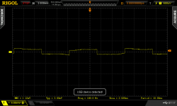
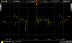
The Tenma result looks horrible.
I wonder how many Builders interpret with their ears and "hear" more detail?
Last edited:
I don't think they use programmable lab PSUs for listening, maybe for initial tests, but many layouts could be ringing a bit, no doubt. Especially when using reg chips having high gain negative voltage feedback op-amps inside.
Sorry Salas, I was talking about the schematic that Kazuo uses.There are two jfets that increase the running current thru the Vref diodes lowering their impedance right?
So if you do not use them is because they are not really necesary there or why?
http://john.asablo.jp/blog/img/2013/06/14/29e379.png
So if you do not use them is because they are not really necesary there or why?
http://john.asablo.jp/blog/img/2013/06/14/29e379.png
The LEDS have lower impedance than diodes so I keep it free of extra circuitry, no Idss matches, and no new current noise sources. Not that all those variations are bad ideas but very specific to Kazuo's system also. C3 is not enough for any 1/F noise filtering for instance that clocks hate, R5 500R lowers the loop gain by 6dB upping Zo x2. For some reason it probably feels better to some sub system of his DAC for him, but its not a general thing. The pcb release is more about whole digital source feeding and must be covering many bases, not be specialized. It also uses much more bias current in the output MOSFET that ups its transconductance. Kazuo uses much less CCS to make mini matrix boards with small sinks bcs he utilizes many. So maybe this is the explanation why he somehow leans to compensate by stronger current gate drive.
I was planning to use 4 regs for a dual mono dac and another 2 regs for the usb-i2s converter ( 1 reg for the clocks ).Since required currents will be between 10-60ma(digital side) and 30-50ma(analog side) for each reg of the dac, for the usb-i2s i will need 200ma and for the tcxo's I think below 10ma.
What current do you reccommend to run thru the ccs's ?
Apart the tcxo's which will run on max 100ma ccs reg, for the other regs I plan ro run 300ma on ccs.If I use them at the reccommended 5V drop will heat a little bit
At what temp your heatsinks rise?(room temp 25C)
What current do you reccommend to run thru the ccs's ?
Apart the tcxo's which will run on max 100ma ccs reg, for the other regs I plan ro run 300ma on ccs.If I use them at the reccommended 5V drop will heat a little bit
At what temp your heatsinks rise?(room temp 25C)
I recommend 0.3A (300mA) minimum setting even for very small loads. For 200mA load I recommend 0.5A (500mA) setting.
For 450mA load (some Buffalo?) I recommend 600mA setting. That should be a max for logical M1 dissipation. Some heat spreads nicely to the mating sink too.
I got a rise of 18C above ambient with 350mA spare current in test. 1.5R R1 and 100R load at 5V. Pretty heavy overhead setting.
That was with 38mm sinks and I "prescribed" 52mm tall ones since I saw them available. Such a reg will need 2U boxes and ventilation anyway.
The Tx will have to be 9VAC or the DC IN 10V to keep the dissipation under control. It won't break even at 80C on the sinks but its more manageable to just stay hot, but not too hot. Ultimately the spare current vs heat is your decision given what differentiation it gives in certain apps to your own ears.
DO-41 diodes will also do for up to 300mA CCS. And even the 38mm sinks but for conservative max CCS and spare. Or with 200mA CCS and 50-150mA spare.
I also added air circulating holes at the bottom of the sinks "chimney" formation. Extra pads for 3rd LED in Rx/J/D for 7V looking good pre-reg uses also.
How to "blindly" set CCS its in the guide on a look up table for fixed R1 values and suggested load ranges. Certain brand LEDS pre-cooked combinations for setting Vout also. The guide is almost proof for release. Few small details to secure and it will be out. The more detailed preparation work we do the best it will serve the people without much confusion. (Hopefully😀).
That is the one that will be in the guide. (The board details and instructions finishing very soon).
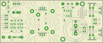
Do you have planned a GB for PCB & parts for Reflektor-D?
Do you have planned a GB for PCB & parts for Reflektor-D?
Yes it will be in the next general GB very soon. All likely parts are tested.
- Status
- Not open for further replies.
- Home
- Amplifiers
- Power Supplies
- The simplistic Salas low voltage shunt regulator