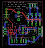
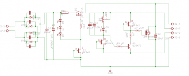
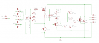
So it would be better to add Rs between Q6 source pin and R7,Q3 node to achieve better hfe of BC847C?
BR,
Ales
Yes. Will work on a straighter portion of the curves.
Rs between Q6 source pin and R7,Q3 node
Aleš, ni OK. Upor mora biti med Q6 Source in stičiščem R7, Q3, kot je Salas napisal.
Ales, it is not OK. Resistor should be between Q6 Source and R7, Q3, as Salas wrote.
Last edited:
The answer probably is in this thread somewhere, but can anybody please tell me how clean the power supply for the SSLV needs to be for optimum results? Is a simple CRC filter sufficient, and how big capacitors do I need?
-It does not "need" to be cleaned with a pre-filter. But it can be beneficial. It can be an active solution like a capacitance multiplier or passive as a CLC or CRC.
-As big as your main filter cap for not using high resistance in the L or R element would be better. Dropping 2-5V over such resistance should be pre-calculated in the Tx secondary rating regarding the CCS setting to be used so to keep a 10V drop across the reg. 7V at least.
-As big as your main filter cap for not using high resistance in the L or R element would be better. Dropping 2-5V over such resistance should be pre-calculated in the Tx secondary rating regarding the CCS setting to be used so to keep a 10V drop across the reg. 7V at least.
-It does not "need" to be cleaned with a pre-filter. But it can be beneficial. It can be an active solution like a capacitance multiplier or passive as a CLC or CRC.
-As big as your main filter cap for not using high resistance in the L or R element would be better. Dropping 2-5V over such resistance should be pre-calculated in the Tx secondary rating regarding the CCS setting to be used so to keep a 10V drop across the reg. 7V at least.
Thank you very much for the answer.
Best regards,
VB
Hello guys !
I power my pcm1794 with ss v1.0(3.3v, 5v) and 3 lipo cells, this way I get between 9.6 - 12.6v at regulators input.
For a while(months) I noticed one thing, when voltage goes below 11v the sound in my speakers goes flat, seems it goes out of weight. Instead when the cells are fully charged the image changes, everything becomes more exploding.
Any explanation ?
You stay nearer the recommended voltage drop across the reg when the batteries are charged. That helps the CCS in the reg to function better.
Hi schultzsch,
It might sound even better with a little more battery,probaly when it gets to 11v it's to low to make it through your regulators and sags below optimum rail voltage,That happens in ac to dc supply's too ,that can be helped with more transformer and more caps. maybe just for fun use a wall wart and see what happens to it then maybe even a varible supply to TEST it! find it's sweet spot and then battery to that voltage!
NS
hi salas, i'm trying to put out 30v to just a pair of jfets in a simple preamp. could i use something lower than 50vac trafo for this? and if i did regardless, let's say with 30vac, would it overheat?
thanks.
thanks.
30V AC secondary is enough for the raw DC in proper level. If you talk VA (power/size) even 20VA would be plenty for a shunt reg for just a TO-92 JFETs pair. Just don't feed it too much spare self current. Check all temperatures are acceptable on sinks and transformer will be enough to set your CCS resistor best.
hi salas, is it recommended to bypass the c6 in the circuit of post #6173?
http://www.diyaudio.com/forums/powe...-voltage-shunt-regulator-618.html#post3634254
http://www.diyaudio.com/forums/powe...-voltage-shunt-regulator-618.html#post3634254
Personally I avoid. But its not destabilizing it if you do. Its just difficult to make a coherent duo with zero resonance when combining small film and lytic.
I had used C0G once (33nF) which I found more agreeable subjectively than a film bypass across the electrolytic Vref filter cap. Taking advantage of its small footprint I kept extra inductance low by positioning directly on the lytic's leads. Leads themselves cut short on both caps.
Hi Salas and all,
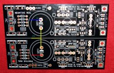
I have a phono stage here with a PS that splits between -24V and +24V for each channel. I would like to use your regs (-/+) fed with a 36V battery in the place of this mains PS. However, the plus and minus lines going into the phono stage share the same return, namely, the umbilical cord between the PS and the phono stage consists of one wire for the +, one wire for the -, and one wire for the return or ground. Would that be OK with your regulators or must the channels be completely independent?
I have a phono stage here with a PS that splits between -24V and +24V for each channel. I would like to use your regs (-/+) fed with a 36V battery in the place of this mains PS. However, the plus and minus lines going into the phono stage share the same return, namely, the umbilical cord between the PS and the phono stage consists of one wire for the +, one wire for the -, and one wire for the return or ground. Would that be OK with your regulators or must the channels be completely independent?
That will be OK since there are no rectifier bridge diodes anymore. You should link the positive side's 0 to negative side's 0 between the now unused main capacitors pad's - & + between positive and negative boards respectively. Midway that link will be your incoming 0 connection point. You could still use main capacitors as bypasses to the battery feed on the other hand, but the no diodes & link things remain.
I'm not sure I understand your second sentence.
You can still use C105, C205 even if having a smooth battery DC input I mean. It can do good bypassing the battery feed. Your preferred quality 1000uF type will suffice.
Attachments
- Status
- Not open for further replies.
- Home
- Amplifiers
- Power Supplies
- The simplistic Salas low voltage shunt regulator


