Maybe some internals in datasheets show clamp diodes and we can estimate? But they don't mention reverse insertion fault endurance usually. It would be useful info.
Not 0.1uF only, small super low ESR films in general will interfere with the fixed Zobel termination of the Bib if there is not much inductance in between to really decouple and will cut a lot of phase margin. They have caused oscillation even. We had a couple of practical examples in this thread where they have caused instability that fixed with their removal. Harsher flat sound like when with EMI interference is a clue. Reflektor is more tolerant but its better without too. You can try without any film on the load's rail, short run of 4 wire cabling, or tantalum rail bypass if it has something to really do there. The shunt reg will damp the load's rail differently than a series one, especially on 4 wire connection.
i'm using bib's 1.2V (with D45) and 3.3V (with bjt) for Ackodac, that has 100uF (electrolyt) and 0.1uF (film) as decoupling on all analog and digital supplies. The wirelength from bib to ackodac is about 2 cm.
What would be the best option.
- remove 100uF an all supplies
- remove 100uF AND 0.1 uF on all supplies?
- drop the zobel filter on bib?
- use 47uF electrolyt cap on bib, and remove 100uF an all supplies?
- different meassures for analog and digital?
Is there any other method to meassure what is best - except listening-test and theoretical reasoning?
Peter
First you should use the oscilloscope. By looking at the rails in AC coupling input switch mode. If you will see no sine wave like oscillations then the system is OK as it is.
If its not I would remove the very small value capacitors first.
If its not I would remove the very small value capacitors first.
Hi Salas!
I would like to use your design with my KumisaIII headphone amplifier. I'm going to need +-15VDC/230mA.
Which version should I choose?
greetings, János
I would like to use your design with my KumisaIII headphone amplifier. I'm going to need +-15VDC/230mA.
Which version should I choose?
greetings, János
Thanks for the response. Do you know where I can find a good pcb layout for the sslv1.1? I would like to design my own pcb with on board transformer, rectifier diodes etc., and as a newbie it"s a great help to have a layout to rely on.
János
János
Will need a little advise from the expert.Lookie lookie, my first reflector powered up, and a little adjustment at the pot, it was dead on 5V, so happy 🙂 Will swap out the Bib with this later for a comparision.
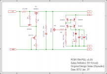
The reflector has been working flawless for 6 months, but when it is compared to my BiB 1.1, I always feel the high is not as crisp. I think I can use some expert advise here. The circuit is based in the a variation of the 5V as in the attachment.
The major changes (as of now) are:
1. The Zobel Cap (C5??) is a 34nf Mica instead of the 0.47uF
2. The 2 x 820uF is replaced by a 2700uF bypassed by a 0.22uf Epcos polypropylene.
3. M2 is IRF610 instead of IRF640.
4. The 2 x 560R are replaced by 1 x 1150R.
Any suggestion to components change to try? The load is no mor ethan 75ma, and the CCS is set to deliver approx 250ma, and the output is 5V.
Thanks!!
Attachments
Wow, that's a supersonic speed response.
Any suggestion to what kind of parameters in the specs to look for and to avoid as well?
I don't have the suggested device but hope I can find some in my bins to use.
Thanks!!
Any suggestion to what kind of parameters in the specs to look for and to avoid as well?
I don't have the suggested device but hope I can find some in my bins to use.
Thanks!!
Hiw does this look? I have the devices in hand for quite test? The Ciss is somewhat high, and Crss is not as good as MTP3055VL.The lower the Crss and the higher the gfs the better.
Thanks!!
Attachments
 Salas
Salas It is no kidding. Just 2 seconds in the intro, I knew the man's guidance was what I had been seeking for the last 3 months!! I have been using the IRFBC40 in my capacitor multiplier a few times but never even thought one second that was what I needed 😱
I am still in denial of how a recycle (yeah, I recycle it from a broken computer power supply) device can provide such dramatic difference!! Even at this early stage, I can say the reflector is at least as good as the BiB.
FWIW, this devices does have lower Vgs than the IRF610. I think it is around 3.7V. So, I needed to adjust the voltage upward. Otherwise than that, it was pretty much clip and solder affair.
Again, thank you, Salas!!
Nice. Its you got nearer the intended parameters now. And you still haven't tried those STP/MTP.
The STP/MTP are in my Mouser shopping cart. So, they will be in my next order once I accumulate enough to commit.
One educational question, why BiB doesn't need a high Gfs shunt device. The irf9610 is pretty low, but it works just fine in the BiB. So, is the choice of the shunt devices a function of the error amp topology? The current mirror requires higher gain device to work wth?
Thanks!!
One educational question, why BiB doesn't need a high Gfs shunt device. The irf9610 is pretty low, but it works just fine in the BiB. So, is the choice of the shunt devices a function of the error amp topology? The current mirror requires higher gain device to work wth?
Thanks!!
There is the IRF9530 in the shunt position officially designated for BIB not the IRF9610.
The reason that Reflektor appreciates better more transconductance in M2 is that it does not have an error voltage amplifier to push it but a mirror "bridge" instead to tell M2 how to current compensate the voltage output to Vref balance. So M2 has to listen easier, needs be sensitive. Its a simpler elegant notion and has no strong phase consequences.
The reason that Reflektor appreciates better more transconductance in M2 is that it does not have an error voltage amplifier to push it but a mirror "bridge" instead to tell M2 how to current compensate the voltage output to Vref balance. So M2 has to listen easier, needs be sensitive. Its a simpler elegant notion and has no strong phase consequences.
Thanks for the explanation, Salas.
It is IRF9530, my memory really isn't what I want it to be 🙂
Sorry for all the questions, sometimes I just have the urge to want to know the why even though things are working. Learning never stops at any age 🙂
Have a happy Thanksgiving to all!!
It is IRF9530, my memory really isn't what I want it to be 🙂
Sorry for all the questions, sometimes I just have the urge to want to know the why even though things are working. Learning never stops at any age 🙂
Have a happy Thanksgiving to all!!
- Status
- Not open for further replies.
- Home
- Amplifiers
- Power Supplies
- The simplistic Salas low voltage shunt regulator