Not direct replacements and surely not in a fixed PCB. D45H is BCE when BD140 is ECB. Make sure you got it connected right. BD140 is for lower currents also. I would not bias it over ~50mA.
it's connected correctly, double checked that yesterday. I have some spare irfp9540, so will try them instead.
BTW where is Q5 in your build's picture? Where that long link from BD140's E pin goes? Is it an earth bus?

So if the TO-92 we see receiving the earth bus is a Toshiba JFET (Q3) it goes to its drain pin. Which is to G,S pins in the schema. Unless its a BF245A. If it is, I suggest you replace it for a Toshiba.
rechecked again 🙂
it's actually Q5 (with red).
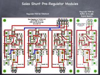
BD140 is connected in accordance to the circuit above and pinout here.
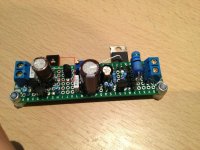
I've already finished 4 working regs. This one is definitely has something wrong in the left part. Most likely some stupid mistake of mine. The layout was taken from Red Baron thread.
it's actually Q5 (with red).
BD140 is connected in accordance to the circuit above and pinout here.
I've already finished 4 working regs. This one is definitely has something wrong in the left part. Most likely some stupid mistake of mine. The layout was taken from Red Baron thread.
Attachments
Kazuo, did you ever try IR LEDS I had talked about as Vref?
No not yet. But if I have a chance ,will try.
Thanks Salas.
Finally, found the error, it turned out to be a surplus jumper that shorted earth with positive rail! 😀 works fine now!
good point to know now is that different manufacturers have different BE pinout on their BD138/140.
thanks again for your help and efforts, Salas!
good point to know now is that different manufacturers have different BE pinout on their BD138/140.
thanks again for your help and efforts, Salas!
How do they measure
I have been searching to see where someone has measured the noise on the output line. I'm sure it is here but search engines do not reveal it and its a long thread to read start to finish.
Anyone know how many nV noise on output?
I see some comparisons of regulators expressed in Noise Density
nV/Sqrt(Hz) Normalized to 100KHz.
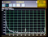
Only a DCB1 power section on an analyzer for 1/f up to 100Hz by a Spanish member. No personal lab analyzer gear available. Those are from a Mezmerize with 100uF Vref cap. Noise density I had shown only by sim unfortunately. #4221 & 4123
Attachments

I have been searching to see where someone has measured the noise on the output line.
PDF on www.linearaudio.net - home website:
http://www.linearaudio.net/images/letters.pdf/V4 JW F7.pdf
Which curve color is the 1.1 and what are the scales?
The PDF's don't come up well in Firefox -- but work well in IE. The scale is nV/RtHz. Here's an image:
An externally hosted image should be here but it was not working when we last tested it.
Dotted orange line at bottom then. Very nice. Super Teddy has an electronic filter for instance.
Thank you. Exactly what I was looking for.
and the Burson has ~60dB more noise at 1kHz
We've decided to call the Burson regulators "euphonic" --
For subjective evaluations everybody has a set of ears and and a gamut of likings and can select. Different applications load characteristics will play a big role also. What we must really thank you for is donating your learned time and specialized gear to enlighten us for the objective part. Those assets very few have and even fewer share. Don't use 0.1uF local rail decoupling on the load's side when applying the 1.1 BTW.
- Status
- Not open for further replies.
- Home
- Amplifiers
- Power Supplies
- The simplistic Salas low voltage shunt regulator