Salas
would you please tell us your recommendation for a Vref element to be used In Reflektor or BIB
also what value of I ccs do you recommend when V out Is 24 V when using STP55 Fet
would you please tell us your recommendation for a Vref element to be used In Reflektor or BIB
also what value of I ccs do you recommend when V out Is 24 V when using STP55 Fet
- Prefer the lowest noise TC compensated Zeners you can find, or a string of LM329s or LEDS. Keep in mind that the noise figures of the ref should be still good at 2-4mA. A TL431 is an option also since there is a big filtering electrolytic.
- 200mA plus load consumption max.
- 200mA plus load consumption max.
cheers,
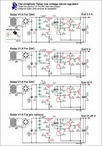
could anyone please confirm that this circuit (att) is correct? It is needed as PS for Red Baron TDA1541 dac. Other circuits work fine (+5V; -5V).
I get zero voltage on the drain after 1st mosfet, does it mean that there is a problem with bc560 (it doesn't look as shorted when tested with dmm).
Would appreciate any help!
Attachments
Those were working specimens as far as I can remember. Maybe you forgot to do the green lines linking in that one?
P.S. Its a BC550 not 560.
you mean Q2? will try then!
and I put no leds as on the initial pic.
No, I mean Q4. Each BJT showing about 0.6V Vbe in circuit and each Mosfet showing 3-4V Vgs in circuit, works.
- Prefer the lowest noise TC compensated Zeners you can find, or a string of LM329s or LEDS. Keep in mind that the noise figures of the ref should be still good at 2-4mA. A TL431 is an option also since there is a big filtering electrolytic.
- 200mA plus load consumption max.
thank you
I ve done reference from led strings only - 12 pcs for a 24 V bypassed with 1000uF - I guess that Is OK
Interesting Is that when I power on regulator the leds start to light after 5 sec
and V out Is 24.1 V after 5 min It Is 24 V
about STP55NF06 dissipation - Not more than 24 V x 250 mA - right ?
The delay is for the small current in the mirror to charge up the big capacitor at a high enough voltage to reach the Leds so its normal.
Your drift is more like one out settling of the Leds than a gradual drift. Very steady.
Its a matter of sinking but more than 0.25A spare will not benefit appreciably in this one. The output Mosfet idles at 6W already. Not trivial.
Your drift is more like one out settling of the Leds than a gradual drift. Very steady.
Its a matter of sinking but more than 0.25A spare will not benefit appreciably in this one. The output Mosfet idles at 6W already. Not trivial.
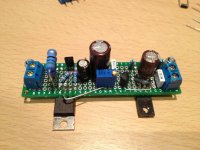
P.S. Show us some photos and what you power with it, tell us how you find it VS what PSU you had, etc.
thank you
my load per regulator Is only 16 mA - one leg of UGS V3 preamp
I ask as heatsink Is very hot
what would you think In that case would be optimal current for STPNF55
my load per regulator Is only 16 mA - one leg of UGS V3 preamp
I ask as heatsink Is very hot
what would you think In that case would be optimal current for STPNF55
There is no arbitrary optimal, its about how much you spend to the load, how much sinking you got and the Vo that heats it up a lot the higher you go. You can afford to save 50mA in your case to make it a bit cooler for instance. Take it down to 0.2A.
P.S. At 24V your Mosfet is far less capacitive than in under 5V builds. That is a good thing.
P.S. At 24V your Mosfet is far less capacitive than in under 5V builds. That is a good thing.
There is no arbitrary optimal, its about how much you spend to the load, how much sinking you got and the Vo that heats it up a lot the higher you go. You can afford to save 50mA in your case to make it a bit cooler for instance. Take it down to 0.2A.
P.S. At 24V your Mosfet is far less capacitive than in under 5V builds. That is a good thing.
thank you Salas
at now I use Hypno boards and plan to upgrade to Reflektor
would you please clear In general bennefit of using more then 200 mA as a ccs
- that Is a demand more to a CCS Fet Instead of output Fet ?
A small reduction in output Z. The CCS FET feeds the output FET with excess current and ups its gfs.
No, I mean Q4. Each BJT showing about 0.6V Vbe in circuit and each Mosfet showing 3-4V Vgs in circuit, works.
Just have checked the reg and it's so as you've stated for Q1 and bc560. Q6 doesnt get any voltage at all. If I measure q1 drain and ground I get zero and on same working reg (but with leds, 2nd circuit) it shows about 5vdc.
I've already replaced q1, triple check the circuit. Damn thing getting me really frustrated😡 Worst scenario I'll replace it with leds if run out of patience...
BD140 has reverse pin order to the one designated on the schematic.
I thought it's (Bd140) a direct replacement to D45H, isn't it?!
If I disconnect the drain of Q1, I still get zero on it. Seems to me the problem is in the left part of the circuit.
I've attached the reg itself and another circuit with bd140 I found some years ago in this thread 🙂
Many thanks for your help, Salas!
Attachments
- Status
- Not open for further replies.
- Home
- Amplifiers
- Power Supplies
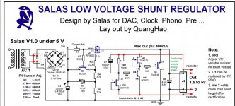
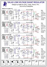
- The simplistic Salas low voltage shunt regulator