I am building a disco 1,2V for DAC
- would you also recommend 2SK117 here (instead of 2sk170) as in bib??
- what mA should i aim at, for the idss at Q5 in error-circuit? (low as possible?)
peter
- would you also recommend 2SK117 here (instead of 2sk170) as in bib??
- what mA should i aim at, for the idss at Q5 in error-circuit? (low as possible?)
peter
Last edited:
sourcing components...
What would make a good resistor for psu (used for DAC)
1) smd ? (for short signalpath)
2) nonmagnetic ?
3) noninductive, noncapacitive ?
4) Else?
What would make a good resistor for psu (used for DAC)
1) smd ? (for short signalpath)
2) nonmagnetic ?
3) noninductive, noncapacitive ?
4) Else?
Low ppm.
low ppm prevents drift of V-out, with rising temperature. But does it benifit performance (noise, Zo etc) in any other way?
Temperature Coefficient of Resistance (TCR) is expressed as the change in resistance in ppm ( .0001%) with each degree of change in temperature Celsius (Co). This change is not linear with the TCR the lowest at +25oC and increasing as the temperature increases ( or decreases). It can be either a bell shaped curve or an S shaped curve. It is treated as being linear unless very accurate measurements are needed, then a temperature correction chart is used. Normally a resistor with a TCR of 100 ppm will change 0.1% over a 10 degree change and 1% over a 100 degree change. The expression of ppm , one part in a million is similar to percent or 1 part in 100 (or percentile)What is TCR ?
Temperature Coefficient of Resistance (TCR) is expressed as the change in resistance in ppm ( .0001%) with each degree of change in temperature Celsius (Co). This change is not linear with the TCR the lowest at +25oC and increasing as the temperature increases ( or decreases). It can be either a bell shaped curve or an S shaped curve. It is treated as being linear unless very accurate measurements are needed, then a temperature correction chart is used. Normally a resistor with a TCR of 100 ppm will change 0.1% over a 10 degree change and 1% over a 100 degree change. The expression of ppm , one part in a million is similar to percent or 1 part in 100 (or percentile)

What would be part voltage-reference-part, with the lowest voltagedrop available wahtsoever?
(probably a silicium diode - but which silicium diode then?)
(probably a silicium diode - but which silicium diode then?)
hi everyone,
is there a reason why a power jfet could not be used in the 1.1SSLV as a shunt device so to have a low voltage output, instead of a BJT?
i just began understanding how the circuit(and electronics in general) work and would like some more insight.
also what charateristics should a good shunt device have? what i understand (if i m not mistaking) is that the higher the transconductance of the shunt device, the higher the gain and the lower the output impedance. i guess it s all a matter of stability,bandwidth,etc. but for instance what does the irfp9240 do well?
not sure that has been discussed before.
Last edited:
It does well decent gfs in decent Crss. A SIT could be tried out, there are considerations of its gfs, Crss, and impact to stability to get to terms as with any other chosen shunt device. Which one you got in mind?
What would be part voltage-reference-part, with the lowest voltagedrop available wahtsoever?
(probably a silicium diode - but which silicium diode then?)
You probably mean a silicon diode? We have used 1N4XXX series with success in some low Vo builds.
well i was looking at the sje120r100 datasheet and thought it may give lower noise, higher Yfs, lower Vgs than a mosfet and i saw it behaved like a mosfet. i think there is a PNP counterpart but i m not sure. i also have a few lu1014d which are less pricey and less available but behave differently.
i m not sure how reverse capacitance can affect anything, i ll have to study what is is first...
i m not sure how reverse capacitance can affect anything, i ll have to study what is is first...
In follower mode the reverse capacitance fully counts. You may apply them parts and test, certainly not out of place. But the SITs are pricey as you said to be relegated in such a hum drum duty I guess. MOSFETs are noisier but there is no voltage gain in that position. Mainly the Vref noise dominates.
About paralleling rather low transcoductance devices don't know, capacitance and parasitic pin inductance accumulating, cost, Rs for current balance upping impedance, doesn't sound like more than a practical way for using up some stock, than specifying a single proper part.
I meant something like a ''figure of merit'' for the job. The possibly higher transconductance along the possibly lowest capacitance penalty.
I meant something like a ''figure of merit'' for the job. The possibly higher transconductance along the possibly lowest capacitance penalty.
ok got it for high Gfs with low Crss.
about paralleling, i thought it might keep Vgs lower at a given total current and maybe alleviate the need for heatsinking ...but i ll take advices of more experienced and knowing person than me 🙂.
i may have an idea on how capacitance and inductances may be harmful(resonance?) in this situation, but i m not sure why we would like the bias to be the same in each shunt device. i also remember having read multiple times that it is desirable to match parallel output devices in the output stage of amps but i m not sure why...could you (or someone else) care to explain? i understand that heat load will be shared even but that is it...
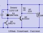
also, i understand that having the lowest possible bias through the bjt (see pic) gives lower output impedance, so i m wondering what obstacles do you encounter when lowering to much the bias. is there a sweet spot? in the pic it is around 4mA depending on the mosfet.
about paralleling, i thought it might keep Vgs lower at a given total current and maybe alleviate the need for heatsinking ...but i ll take advices of more experienced and knowing person than me 🙂.
i may have an idea on how capacitance and inductances may be harmful(resonance?) in this situation, but i m not sure why we would like the bias to be the same in each shunt device. i also remember having read multiple times that it is desirable to match parallel output devices in the output stage of amps but i m not sure why...could you (or someone else) care to explain? i understand that heat load will be shared even but that is it...
also, i understand that having the lowest possible bias through the bjt (see pic) gives lower output impedance, so i m wondering what obstacles do you encounter when lowering to much the bias. is there a sweet spot? in the pic it is around 4mA depending on the mosfet.
Attachments
Last edited:
- Status
- Not open for further replies.
- Home
- Amplifiers
- Power Supplies
- The simplistic Salas low voltage shunt regulator