It's not clear, when you said 5V across R1 is the dummy load right?
Oh - that's the trouble! The 5V should be across R1, which is the current-setting resistor.
The dummy load goes in the place of the Heater of the 6922. The voltage across the dummy load should be 0,3 x R(dummy).
The dummy load value is not too important, it's just to check that the current is correct.
When you connect the 6922 the voltage should be about 6,1 to 6,2V - BUT you may need to make small changes to R1 until it is correct.
Please ignore the Quanghao drawing, unless you want to change to a much lower power supply, and use this totally different circuit!
If you have a 17-18V supply, 9,2V across the LEDs, you should be OK. Just check for 5V across R1, then change the value of R1 until you get 0,29 to 0,30A
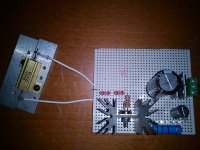
With R1 15R & dummy load 16R I read 1.99V across the dummy load & 1.85V across R1
If you get 1.85V across R1, and you have 9.17V across LEDs, then the FET gate voltage is 7V. That does not sound right!
One possibility is that the circuit is oscillating. This can give confusing readings on a DVM! Do you have a big capacitor on the supply voltage, right near the circuit?
One possibility is that the circuit is oscillating. This can give confusing readings on a DVM! Do you have a big capacitor on the supply voltage, right near the circuit?
With R1 15R & dummy load 16R I read 1.99V across the dummy load & 1.85V across R1
1.99 / 16 =~ 124mA.
If you get 1.85V across R1, and you have 9.17V across LEDs, then the FET gate voltage is 7V. That does not sound right!
One possibility is that the circuit is oscillating. This can give confusing readings on a DVM! Do you have a big capacitor on the supply voltage, right near the circuit?
Yes
Attachments
Quanhao schematic is NOT OK. There is likely to be stability problems, if you build the circuit like that.
I notice that Quanghao is attempting to sell filament regulators on his site, using design elements copied from my DIY kit filament regulators (he bought one last month to get a closer look). I should make it clear that, although he is using my description "Gyrator + CCS" filament regulator, this circuit is not designed by me, nor am I able to support it. AND, If the snapshot above is used in the regulator, there is VERY likely to be trouble from oscillation, and other effects as well.
The parts of the design taken from my kits were used without the politeness of asking if it was OK.
Typical Quanghao move. I would like to add another warning to everybody. Quanghao often makes mistakes in his schematics. If you can get over the ethical issues and will get boards/kits from Quanghao, make sure you check the schematic thoroughly.
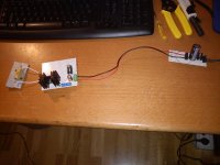
OK to have PSU/diodes separate, but please take care that you have 1000uF near to Q1.
If the circuit is stable (is not oscillating), you should have 4V (approx) across GATE- to SOURCE of the IRF9610.
If you have 7V here, I suspect FET trouble, or oscillation. If you bring a AM-radio nearby (tuned to a weak station), do you hear the radio crackling, when the circuit is powered ON?
If the circuit is stable (is not oscillating), you should have 4V (approx) across GATE- to SOURCE of the IRF9610.
If you have 7V here, I suspect FET trouble, or oscillation. If you bring a AM-radio nearby (tuned to a weak station), do you hear the radio crackling, when the circuit is powered ON?
OK to have PSU/diodes separate, but please take care that you have 1000uF near to Q1.
If the circuit is stable (is not oscillating), you should have 4V (approx) across GATE- to SOURCE of the IRF9610.
If you have 7V here, I suspect FET trouble, or oscillation. If you bring a AM-radio nearby (tuned to a weak station), do you hear the radio crackling, when the circuit is powered ON?
Is not 1000uF is 100uF 25V.
I have 7.3V gate-source irf9610
DCin 15.84V rectified & filtered
You had 17.67V before - where did nearly 2V go???
DCin 15.84V rectified & filtered
what changed?12V TX = 17.67V rectified & filtered
Is not 1000uF is 100uF 25V.
I have 7.3V gate-source irf9610
Please try increase from 100uF to 1000uF, or you may get oscillation.
7.3V is not right! I think this is a measurement problem, caused by oscillation.
Only diodes: before Fairchild FFP04H60S 4A 600V & now Fairchild Stealth II FFPF60SB60DS 4A 600V
something is seriously different.only diodes
Read Rod C.
Have you read Jung yet?
seriously an LM317 and one resistor gets you most of the way there.
something is seriously different.
Read Rod C.
Have you read Jung yet?
seriously an LM317 and one resistor gets you most of the way there.
Yes I know: I have installed now something similar but I want to try this other way.
Now it's a challenge for my.
Do you have some Schottkys at hand? This will make the voltage just right.
I have:
Fairchild UF4007 1A
Vishay 1N4007 1A
Better to go back to the parts that gave 17.7V.
Add some capacitance to the dc supply right near IRF9610 circuit.
Then, find why the gate-source voltage is so high. Any chanc of oscilloscope?
Add some capacitance to the dc supply right near IRF9610 circuit.
Then, find why the gate-source voltage is so high. Any chanc of oscilloscope?
- Status
- Not open for further replies.
- Home
- Amplifiers
- Power Supplies
- The simplistic Salas low voltage shunt regulator