yes i know that would be optimal but the thing is that with two seperate amp boards for left and right channel, i think it s pretty much the same to just put the reg as close as possible to the amp boards with short wires, no? we have to consider the size of the amp board in my opinion also
i agree that for a device that has everything on one board, it s more convenient. but in my case there still will be a good lenght of wire left, that the sense wire wont have control upon. i dont know if you get me?
so my theory is that i m better off with one reg for each board, or no sensing wires at all keeping short connections.
what do you think?
I think that double mono symmetric 1.2s and to sense each amp from its own reg where the most important consumption and grounding nodes are on each amp's PCB, that would be optimum. But we can always connect best possible what we got. Post even a cellphone camera picture of your amps and shunts placed as you find handy for inbox construction, so we can think of best compromise.
sense leads should sense where the paralleled outputs leave the single track output. Design the single traces routes as close to the amp boards as possible.
Then put the amp boards as close to the sense points as possible.
Do not sense one board while another board is the load. The signals at one board could be out of phase from the needs of the other board and the reg will make the wrong corrections.
Then put the amp boards as close to the sense points as possible.
Do not sense one board while another board is the load. The signals at one board could be out of phase from the needs of the other board and the reg will make the wrong corrections.
what can bc556b be replaced with in the schematic post 2432 until i receive them?
bc557,bc560c?
i blew that minus reg again😕
bc557,bc560c?
i blew that minus reg again😕
BC557B. How you blew it? BC556B put again because it gives same gain with the positive branch.
to make a long story short, i wanted to test it because because i heard a joint breaking apart under the board, and i puted -66V into the reg by mistake.dont have any b grade pnp bjt with me so it s going to wait i guess.
now i begin to realize the problem might more be my impatience. i remember my teacher saying courage and patience were the best virtues. now i guess it takes all it s sense!
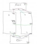
also, attached is what i had in mind for my amp (beta22). i think that way remote sensing is unnecessary, with the boards very close one to each other. maybe there is a founding mistake or two but the idea is there
now i begin to realize the problem might more be my impatience. i remember my teacher saying courage and patience were the best virtues. now i guess it takes all it s sense!
also, attached is what i had in mind for my amp (beta22). i think that way remote sensing is unnecessary, with the boards very close one to each other. maybe there is a founding mistake or two but the idea is there
Attachments
Last edited:
Use something PNP in hand loosely compatible for now. You substitute best soon.
I would connect 0 from regs at one mid point between the 2 amp channels. Can connect their 0s with a thick copper wire and bring the regs 0s on its middle.
I would connect 0 from regs at one mid point between the 2 amp channels. Can connect their 0s with a thick copper wire and bring the regs 0s on its middle.
i m sorry i m having a hard time undertanding what you are trying to say. could you rephrase that please?
@Salas
For V21.2 in +56V out +46V I know that I can substitute Q1 IRF9610 for IRFP9240 OR IRFP9140 but wich is the substitute for Q4 IRF9540?
@Rcruz
As I understood you don't use R13 & C3 in the V1.2, that's correct?
For V21.2 in +56V out +46V I know that I can substitute Q1 IRF9610 for IRFP9240 OR IRFP9140 but wich is the substitute for Q4 IRF9540?
@Rcruz
As I understood you don't use R13 & C3 in the V1.2, that's correct?
irf9540 is a 100Vds FET.
Why do you think it needs changing when Vsupply = 56Vdc +- tolerances.
Why do you think it needs changing when Vsupply = 56Vdc +- tolerances.
@Salas
For V21.2 in +56V out +46V I know that I can substitute Q1 IRF9610 for IRFP9240 OR IRFP9140 but wich is the substitute for Q4 IRF9540?
@Rcruz
As I understood you don't use R13 & C3 in the V1.2, that's correct?
IRFP9240/9140 for IRF9540 if you got TO-247 in inventory. Ricardo uses TO-220 CCS and TO-247 shunt MOS I think.
He uses 47uF Silmic II instead, after my suggestion so to be on the safe side as he is without a scope, thus not able to check if the Zobel would be enough with his layout and load for no oscillation, and/or tweak. Don't use super low ESR output capacitors if you will go lytic. 22-47uF medium ESR if you want to evaluate values and brands/types. Somewhat slower approach than a smaller film and R, but safe.
47uF Silmic II instead the zobel network C1 33p + R14 1.2K?
I have on hand Cerafine 47uF/63V can I use instead the Silmic II?
Can't use R13 1R & C3 4.7uF MKP?
I have on hand Cerafine 47uF/63V can I use instead the Silmic II?
Can't use R13 1R & C3 4.7uF MKP?
Last edited:
33p+1.2k you stay away!!!🙂 Very crucial and non tweak lead-lag internal feedback compensation step network.😎
I am talking lytic instead of R13+C3. Yes, try Cerafine too. You can also use R13+C3 and decide. Its faster if it cooperates OK.
P.S. What are you cooking?😀
I am talking lytic instead of R13+C3. Yes, try Cerafine too. You can also use R13+C3 and decide. Its faster if it cooperates OK.
P.S. What are you cooking?😀
I will use for shunt Q1 & Q4 IRFP9140 & that I have on hand, I have all semis & caps, only need the 33pF & some resistors that will order asap.
- Status
- Not open for further replies.
- Home
- Amplifiers
- Power Supplies
- The simplistic Salas low voltage shunt regulator