sorry i meant Vin related to ground.
also, i dont have B grade bjts with me right now. so if i want a -30v reg with bc557 for q2,q9, do i just have to lower r14,r15? does it make sense?
For -30V B- the 3.3k R14,15 value is OK for about 5mA through the LED. Keep em. BC557 will work in the cascode tail too, its only a little noisier than BC560. Not crucial in those positions.
For Vin to ground potential there is nothing to plan. Those BJTs in cascode will surely take it, they got much max. Vin is a relation to Vout and must be 7-10V more than Vout as a nice margin. Nothing else.
just to be sure:
irf540n as shunt fet and irf540 as ccs fet, two different manufacturers is ok?
PLAIN bc557 as q2,q9 is ok?
i checked my wiring many times and all my transistors tested good.correct led orientation. i m in total disbelief...
irf540n as shunt fet and irf540 as ccs fet, two different manufacturers is ok?
PLAIN bc557 as q2,q9 is ok?
i checked my wiring many times and all my transistors tested good.correct led orientation. i m in total disbelief...
Last edited:
I wouldn't think there is a problem with manufacturers, me I have used IR TO247 and TO220 Mosfets only though.
Go ahead use what you got, BC557 I would not be suspicious of too, and we will see.
Go ahead use what you got, BC557 I would not be suspicious of too, and we will see.
guess what?
it works!
hi five Salas! we made it!
it suddenly worked when i replaced the irf540s by irf240s. might be it but might be not too.
have you tested the reg with them irf540?
it works!
hi five Salas! we made it!
it suddenly worked when i replaced the irf540s by irf240s. might be it but might be not too.
have you tested the reg with them irf540?
Last edited:
guess what?
it works!
hi five Salas! we made it!
it suddenly worked when i replaced the irf540s by irf240s. might be it but might be not too.
have you tested the reg with them irf540?
Which one works? With the BJT cascode, or with the Jfet cascode? Any pics?
Up to now IRF9610+9540, IRFP9240+IRFP9240, IRF9610+IRFP9140 have been used in the positive, IRFP240+IRFP240 in the negative. IRF540N is very near to the IRFP240 for Ciss, weird. Are those 540s testing OK now you got them off board? Maybe you had some nut n' bolt insulation issue with those TO-220s? The TO-247s have insulated mounting eye.
Which one cct you made? The minus BJT casc example #2432?
Congrats.
i ve got an hybrid reg!
+ is jfet cascode(irf9540)
- is bjt cascode(irf240)
i dont have a camera, one day i ll buy one and upload pics. i promise (well i ll try hard 🙂). but i can say it looks a lot like salas' on page 190.
yes maybe when putting the new mosfets, i corrected a bad link.i ve put an insulation washer already so it wasnt it. but those irf540 are still good as far as my Vgs test says.
in the end i m still unsure if it s me or the mosfet.one thing though, i always tested the reg at around 14Vin. so maybe irf540 is not suited for lower voltages? i dont know. i may try again though in my next build which wont be too far off (weeks probably). anyway, i ll keep you updated.
congrats to everyone who worked on this shunt also. it s sounds better in every way than my sigma22 (amp duty) as far as i can tell. sound is smoother and more detailed. reminds me of when i switched to battery once for an analogue reg in my dac. same kind of improvement.
i m afraid about stability issues on my hybrid though. i m gonna go full bjt cascode. i was so happy i had to hear what it was capable of!
Last edited:
You did hear it also, you are fast! Cellphones got cams too these days... They are not different in performance analysis if having the JFETs for Cascode or the BJTs. The BJTs allow higher Vout settings mainly, and they have a led glowing ''on'' too. OK you avoid selecting JFETs too, BJT casc 4 more components. Working for 9540 and not for 540 still is weird to me. IRFP240 not really different in key points too. Some marginal layout or stopper issue maybe, favoring the latter. You use coax for remote sensing, yes? What kind of machine it powers?
P.S. Have just looked to sigma22, what you had was no slouch. Happy that your effort brought you substantial subjective benefits. Happy listening.
P.S. Have just looked to sigma22, what you had was no slouch. Happy that your effort brought you substantial subjective benefits. Happy listening.
no. no remote sensing for now as i have to modify my amp wiring a bit. it is a 2 channel beta22, for my not-boxed-yet pm6c and and hd595.
dont quite exactly what gate stopper means, i m only at the beginning of my diy journey🙂
there is a chance though that I did a routing mistake, not the irf540.
anyway, everything is fine now, except maybe i ll need bigger heatsinks, but that s another story.
next on my list will be to build stormtronic-ikoflexer 3.3V reg... VS ad797 flea 🙂
BTW ikoflexer, thanks for the little program.
edit=Pm6c
Last edited:
You did hear it also, you are fast! .
i only changed the cascode on the neg. reg
no. no remote sensing for now as i have to modify my amp wiring a bit. it is a 2 channel beta22, for my not-boxed-yet pm6c and and hd595.
dont quite exactly what gate stopper means, i m only at the beginning of my diy journey🙂
Expect a further resolution and definition upgrade when you will wire it for remote sensing.
Gate stoppers are those 120R feeding the Mosfet gates. Base stoppers when feeding a BJT base, grid stoppers when on tubes. They counteract oscillation tendencies by locally damping the capacitive gates against forming resonant tanks with the layout inductances. Their legs must be very short to the gates, same for gate legs, and better be carbon 1/4W if you can get.
See post 2402 on previous page. Use only one led in Vref, use the MJE350 as shunt element (watch pin out), and remember to change the R6 220R gate stopper to a 10R base stopper. Also take out the 0.1uF cap from paralleling the output cap, it actually worsens the phase margin. Maybe you will need a larger value trimmer, or 100R-220R in series with it.
P.S. The schematic you posted is going to mislead you for Mosfets pin out in the positive branches. Use post 2402 as a guide. Where gate=base, drain=collector, source=emitter, for the shunt element substitution. MJE350 is opposite for a ready made board unfortunately, as is BD140. Look for D45H8 that will fit for pins a ready made board for GDS Mosfets.
Yes it´s working now giving 3,3v to my diy DAC.I had to use a 100 trimpot in series with the original one.When using only the original pot I got 2,5v and then with a quarter turn it was up in 10v..But now it works fine.
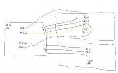
So, you want to power 2 channels from one symmetric shunt? Because I don't understand the sketch. You show four Vout polarities.
yes sorry i should have made that a bit clearer.
the 2 sets of Vout are connected togheter. i m just using 2 seperated terminal blocks. i dont know if the whole idea makes sense though...
the 2 sets of Vout are connected togheter. i m just using 2 seperated terminal blocks. i dont know if the whole idea makes sense though...
Last edited:
yes i know that would be optimal but the thing is that with two seperate amp boards for left and right channel, i think it s pretty much the same to just put the reg as close as possible to the amp boards with short wires, no? we have to consider the size of the amp board in my opinion also
i agree that for a device that has everything on one board, it s more convenient. but in my case there still will be a good lenght of wire left, that the sense wire wont have control upon. i dont know if you get me?
so my theory is that i m better off with one reg for each board, or no sensing wires at all keeping short connections.
what do you think?
Last edited:
Hi,
What the noise level of Salas low voltage shunt regulator ?
I'm Looking for 5V and 3.3V regulator with 200mA maximum capability
that will be better than Operation with batteries power supply.
Suggestions are welcome 🙂
What the noise level of Salas low voltage shunt regulator ?
I'm Looking for 5V and 3.3V regulator with 200mA maximum capability
that will be better than Operation with batteries power supply.
Suggestions are welcome 🙂
Hi,
What the noise level of Salas low voltage shunt regulator ?
I'm Looking for 5V and 3.3V regulator with 200mA maximum capability
that will be better than Operation with batteries power supply.
Suggestions are welcome 🙂
noise sims on page 190.
for 3.3v:
http://www.diyaudio.com/forums/powe...ake-discrete-shunt-voltage-regulator-114.html
notr sure it can do 200ma without mods though
- Status
- Not open for further replies.
- Home
- Amplifiers
- Power Supplies
- The simplistic Salas low voltage shunt regulator