If can't put in a separate box, only two solutions in the same box:
-R-Core Tx: Selectronic - France
-Sheet of permalloy Mu-Metal connected to ground covering all phono RIAA pcb's, you can buy here: Ultraperm MUMetal Shielding Sheet 0.15mm, 31.5cm x 19.5cm 80% nickel | Diy HiFi Supply
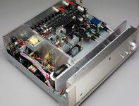
Today I bought some 100x100mm ferrous plates in a local AKI store... I tryed them using a magnet so these are iron based plates 1mm.
I connected the plate to earth using an aligator shunt and moved the setup around the riaa board.
It seems the total psu should be "nested" because I get the best results by shielding the tx + rectifier + smoothing cap 🙂
Shielding the TX alone makes only a small difference.😕
Due to lack of space, I was not able to test the magnetic current inducing effectcs on the shunts .... any comments ?
PS:
After some burning time, the sound is really opening up... piano is unbelieavably good.
Using coax I noticed a big difference in noise floor regarding Cat5 twisted pair.
With coax the v12 is really quieter than the v1.
V1 is good to impress and if you are not using top of the line anxiliary equipment (power amp + speakers) it will help with very sure body, attack and good soundstage.
V1.2 is another league..... If you have a good setup (able to transduce all the detail with aplomb) then you begin to hear the real size picture !
Splendid work Salas !!!
That shows that you got enough wire AC loop area in proximity to high gain. Both Riaa and shunts are high gain. Shield the right hand side, positive move by all means.
So That is why I get such low noise with the external psu on the other riaa where the TX + rectifier + cap are on a separate box !
Nevertheless it is funny that such a small shield should reduce noise so much !
(I have an old aiwa tape deck that has a big case. The tx is placed on one corner with a small iron plate in the vertical in front of it... maybe I need only a small well placed shield)
BTW, I like the Parasound approach. (Is he using shunts ?)
Attachments
Last edited:
John is using local cap multipliers and series pre regs I think he wrote as a member here, in his Vendetta at least.
hi everyone,
in the 56v reg v1.2,
if i want the neg version, is it exercise as in the 25v version?
i.e.
1)interchange bjts channels(n to p and p to n)
2)invert q5 and r12 chain
3)flip q6 the same way as the 25v version
4)interchange d1 and r7, and faces up
5)r-11 goes above q9
6)irf540 as mosfets
is nthat correct?
John is using local cap multipliers and series pre regs I think he wrote as a member here, in his Vendetta at least.
So in the Vendetta he uses gyrators and series regulators ?
If I recall correctly I think he mentioned in some posts in that long thread Blowtorch probably.
Not a bad approach... I am using gyrators before serial sregs in the CDP.
IMO shunts are better... the only drawback being the heat 🙂
IMO shunts are better... the only drawback being the heat 🙂
IMO shunts are better... the only drawback being the heat 🙂
Hehe, move to Sweden... we also need people in our Northern Territories 😀
I do! 🙂 But it's hard to follow the story without any words.
i already have my hands full trying to make salas shunt work...and you want me to add words to make the thing look even more messed up? 🙂😉
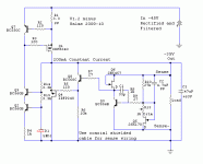
seriously i m just trying to understand how the negative 56v(p192) reg would LOOK like. i dont quite know yet how to upload ltspice schematics
seriously i m just trying to understand how the negative 56v(p192) reg would LOOK like. i dont quite know yet how to upload ltspice schematics
Last edited:
LED has correct orientation in your sketch but it should remain down along that resistor.
See a mirror negative example.
thank you!
i ll try it out and cross my fingers...
seriously i m just trying to understand how the negative 56v(p192) reg would LOOK like. i dont quite know yet how to upload ltspice schematics
I use this little program
Mirek's Free Windows Software
LED has correct orientation in your sketch but it should remain down along that resistor.
See a mirror negative example.
what minimum voltage Vin it should be fed with (smallest potential difference) ?
- Status
- Not open for further replies.
- Home
- Amplifiers
- Power Supplies
- The simplistic Salas low voltage shunt regulator