So this must be better!?
I have added some holes under the 5W R´s. Just for the safety. 😛
This one looks more practical, yes. If there aren't any wrong connections, it will do.
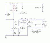
Plan for 10V Vin - Vout, makes it run better for rejection and mains tolerances. 9-5V diff is little. Just the Vgs. This version works stable on all layouts, just double check there is no connections mistake against the schematic. If you could just bring the gate stoppers very near to the MOS gates would be nice though.
18Vin to 15Vout is only 3Vdrop.
Similarly 12Vin and 5Vout is only 7Vdrop.
As Andrew said. Don't forget a healthy DC Vdiff In-Out.
18Vin to 15Vout is only 3Vdrop.
Similarly 12Vin and 5Vout is only 7Vdrop.
? Is it not ok ?
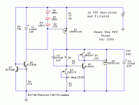
Are there any advantages in your new Dec. 2009 design to the 2008?
BTW, could someone tell me if the IRSP9240 TO247 fits in a SK104-25,4 STS heatsink?
BTW, could someone tell me if the IRSP9240 TO247 fits in a SK104-25,4 STS heatsink?
Attachments
Last edited:
Apart from the resistor being a more reliable ref considering noise against average zeners, the right one is the same. It only uses a ring of two BJTs instead of a Jfet in the CCS tail for max voltage reasons. Its a 45V out schematic. It uses a lower Idss Jfet than a BL for thermal reasons of the TO-92 BJT underneath at nearly such vce, as well.
!
This is the board, copper is 2oz!😀
This is the board, copper is 2oz!😀
An externally hosted image should be here but it was not working when we last tested it.
Shortly back to the TX Vin. Better to take 15V & 21V instead of 12V & 18V?
BTW, these R-Core transformer at selectronic.fr looks really nice.
BTW, these R-Core transformer at selectronic.fr looks really nice.
Apart from the resistor being a more reliable ref considering noise against average zeners, the right one is the same. It only uses a ring of two BJTs instead of a Jfet in the CCS tail for max voltage reasons. Its a 45V out schematic. It uses a lower Idss Jfet than a BL for thermal reasons of the TO-92 BJT underneath at nearly such vce, as well.
Hi, Salas,
I am about to build/rebuild yours and Iko's this coming a few days with my newly designed, more compact PCBs that have shorter track paths. After my earlier experiments now I am gettong on the real builds. I have already purchased the parts for a couple of regs for both yours and Iko's, and my 4 way active XO line level circuit needs at least 3 regulators. 4 would be better if they fit the chassis.
These regulators sound excellent as I reported earlier. Last time when I built yours I used the BC550c buffer. You mentioned that with the buffer the high was more smooth. I am wondering why you have not put it into your latest schematic. My question is, are there any advantages of using the buffer that outweigh any disadvantages, objectively and subjectively?
When playing with Iko's I realized how much sound improvement it made by using remote sensing. I have not tried remote sensing on yours. This time I have a new PCB design with remote sensing and have a oscilloscope to assist! I am sure I will get very good sound out of it. I am only struggling if I would put the buffer in or not. By looking at the simulation, the impedance is already low enough up to 20kHz. I am not sure if pushing it higher with the buffer is needed, provided that I have a very quite raw supply (possibly over 100dB rejection before the regulator), and no high frequencies get into the circuit (e.g. with low pass filters)
Regards,
Bill
That is not a latest design, just adaptation for 45V. Remote sensing works for the subjectively better on it too and without problems as Ricardo Cruz reported. The buffer is a 1.1 advance that needs careful placement as you know. It pays back in more resolution too IMO, can be a bit ''lean'' in systems needing 1.0's ''roundness'' more, though. It worked in different gain and B+ 2 phonos of mine, and in your dual reg on OpAmps for the better, but Ricardo for instance had oscillations in his layout and got some of the performance lift by choosing the remote sensing route in the end. So the standard for all should be the easy 1.0. Its SUV all terrain, well received and liked. I recommend remote sensing on that for some carefree improvement when with a bit of excess wire. OTOH you have no reason to go a step back. Remote sensing may cover more ground towards your sonic blend goals and is worth testing on your dual 1.1. It is just the more things we add, its getting more technical, stability margins narrow, and becomes less plug n' play. Also taking out the buffer and reverting to 1.0 for a comparison is a piece of cake. Just a jumper.
Regards
Regards
Hi Salas,
one last question 😱
I saw schematics with and without C1 over the three LED´s. Is therefor a specific reason?
Thanks for your great help!
one last question 😱
I saw schematics with and without C1 over the three LED´s. Is therefor a specific reason?
Thanks for your great help!
Even with 10cm lenght cables, the four wire version (sense wires) proved much more detailed and with better transient control. 🙂 (Tone is the same)
Hi Salas,
one last question 😱
I saw schematics with and without C1 over the three LED´s. Is therefor a specific reason?
Thanks for your great help!
In some it helps enough with ripple rejection, in others not that much. Whatever does not contribute much I skip it.
- Status
- Not open for further replies.
- Home
- Amplifiers
- Power Supplies
- The simplistic Salas low voltage shunt regulator