I like glowy things too, soo preeety 😉 but yeah no joke I like the odd LED reference, I tend to prefer them to regular diodes.
but then most of my regs do tend to be of a fairly low voltage
but then most of my regs do tend to be of a fairly low voltage
I have measured today some LED's, it's green led's with Vf 2.02V at around 6mA current through them. Also, I measure current throgh the 2SK170GR, one had 4.3mA and second 5.7mA. Next week I will buy some new part and measure them.

Finished the rectification / smoothing module for the 37v shunt. Works perfectly with the 36v R core 🙂 No mechanical noises.
I am using the same shunt I built for 28v and only changed vref resistor.
Should I verify BC550c temp ?
Ricardo
I am using the same shunt I built for 28v and only changed vref resistor.
Should I verify BC550c temp ?
Ricardo
Not as it is. Needs to set the currents higher and build 2 negative ones. One with a larger secondary & trimmer for your -15V.
Not as it is. Needs to set the currents higher and build 2 negative ones. One with a larger secondary & trimmer for your -15V.
Sure, i need to make a new layout. Did you have some values for the higher current and the -15V trimmer?
BTW, is a 18V AC secondary enough for this line or do i need a 21V AC?
Also i would like to make an externe psu with much more capacity per line (~50.000µF).
So it would be also interesting to know how much VA the transformer should be.
I have no problem to oversize this on.
Last edited:
18VAC is OK. Circa 2k5 trimmer will get it to -15V. R1 under 10R normally gives more than 200mA, depends strongly on the LEDs Vf. Must be 5W. Try 6R8-8R2, see the Vdrop on it and calculate the running current with Ohm's law. The spare current burns on the sinks, remember. Leave at least +20% over the load needs to burn. Tx VA goes along voltage and current burned, and is good to be x2. Beyond that it is anecdotal and subjective.
Never had too much temp in the 36V for that. Why, you feel some BJT is hot to touch?
No... just warm at the touch.
It was just a thought 🙂
@ quanghao
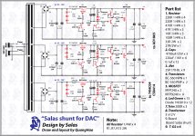
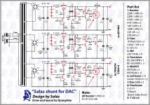
I think in your schematic is a small bug. The IRFP9240 is upside down 😱
The bridge polarity D5, 6, 7, 8 is wrong too.
6R8 to 10R in TOTAL. 6R8/3 is going to set too much current which will lead to heat. If you find it better with 3 resistors for heat spread, part size etc, check with 33R or 27R 2W X3 in parallel and if its not as much as you need go 22R 2W X3 in parallel, better make it stronger only on the one you need the most current. Be conservative, the excess is burned on the sinks, and you only have local ones up to a size.
Plan for 10V Vin - Vout, makes it run better for rejection and mains tolerances. 9-5V diff is little. Just the Vgs. This version works stable on all layouts, just double check there is no connections mistake against the schematic. If you could just bring the gate stoppers very near to the MOS gates would be nice though.
Plan for 10V Vin - Vout, makes it run better for rejection and mains tolerances. 9-5V diff is little. Just the Vgs. This version works stable on all layouts, just double check there is no connections mistake against the schematic. If you could just bring the gate stoppers very near to the MOS gates would be nice though.
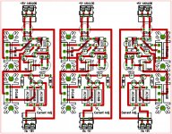
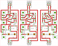
So this must be better!?
I have added some holes under the 5W R´s. Just for the safety. 😛
I have added some holes under the 5W R´s. Just for the safety. 😛
Attachments
Last edited:
- Status
- Not open for further replies.
- Home
- Amplifiers
- Power Supplies
- The simplistic Salas low voltage shunt regulator