you can see the Salas shunt in my room!
http://vnav.vn/forum/viewtopic.php?f=21&t=29614&start=350
I know you dont have nick, I think you can use my nick!
ok or no??
Thank you again!
http://vnav.vn/forum/viewtopic.php?f=21&t=29614&start=350
I know you dont have nick, I think you can use my nick!
ok or no??
Thank you again!
Thank!
you can sent for me your Adress, an E-mail??
My E-mail : **************
Quanghao
Thank you for wanting to give me a gift. But as I wrote before please DO NOT post personal data on open forum, emails and addresses can be used for spam by spam robots.
Thank you for wanting to give me a gift. But as I wrote before please DO NOT post personal data on open forum, emails and addresses can be used for spam by spam robots.
Ok! you can sent for me to email:
mythuat818 g mail . com
i use G mail point com!
you try sent ! thank
E: mythuat818 g mail . com!
you can see the Salas shunt in my room!
http://vnav.vn/forum/viewtopic.php?f=21&t=29614&start=350
I know you dont have nick, I think you can use my nick!
ok or no??
Thank you again!
Is that a Vietnamese audio board? Can't see pictures, and it is not proper to register as you. Please don't post your login data here. Just more pictures if you have from that room. And some words about what DAC you compare with, what psu had before, some people maybe look for a simple dac + regulator.
Ok! you can sent for me to email:
mythuat818 g mail . com
i use G mail point com!
you try sent ! thank
E: mythuat818 g mail . com!
OK, OK, gift accepted. Thanks for your enthusiasm.🙂
Is that a Vietnamese audio board? Can't see pictures, and it is not proper to register as you. Please don't post your login data here. Just more pictures if you have from that room. And some words about what DAC you compare with, what psu had before, some people maybe look for a simple dac + regulator.
OK!
I see! thank
OK, OK, gift accepted. Thanks for your enthusiasm.🙂
hi! Salas you sent your information to me by e-mail! Im waiting you!
Thank!
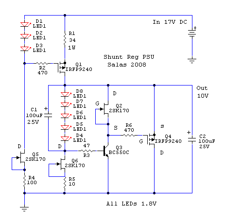
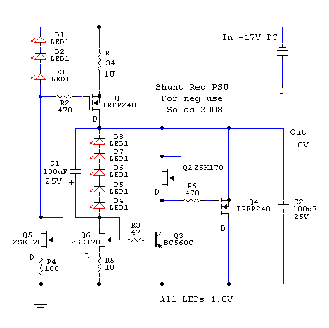
Have a look at these two.
Edit: this is V1
Hi Iko
I noticed that you placed the cap over the leds so that it connects between the ccs and the 100r.
I am using a different layout where the cap is used to bypass only the leds.
Why the difference ?
Ricardo
Ricardo, you can do it both ways. My simulations show better psrr this way, so I just got used to draw it so. My intention was to put in one post the dual rail salas v1. I will change it now so it is the way he intended (sorry salas!).
Reload the web browser page, have a look at the capacitor position.
Edit: to eliminate any further confusion, those images now will show the circuit drawn by salas. Lesson learned for me, I'll avoid drawing other people's circuits, it's too easy to create confusion.
Edit: to eliminate any further confusion, those images now will show the circuit drawn by salas. Lesson learned for me, I'll avoid drawing other people's circuits, it's too easy to create confusion.
Last edited:


I am trying to look for an answer for Ricardo and myself.
I have started reading this thread and a couple of related threads and may have gone through the first a few dozen pages now.
Seriously I am looking for that “perfect” line level regulator as I have yet to find one. This Salas v1 looks pretty good to me and am giving me new hope.
The only thing I am worrying about is C2, the 1000uF electrolytic capacitor. It is there to suppress the noise of D1, the zener or a string of LEDs that provide a voltage reference. I have no reason to have any doubt on Iko’s measurements, which showed that C2 cuts out all the “grasses”.
So why would we need such a large value of capacitance in cutting the grasses? The 1N47XX datasheet shows the impedance of a zener is about a few hundred ohms with some given currents. C=1 / (2*Pi*R*F). The low impedance requires a large capacitor to give an adequate corner frequency. I guess 1000uF would be the largest you would go, as any higher value may cause detrimental effect on some active device when powered on.
A 1000uF capacitor would have an impedance well under 1R within the audio band, and in the case of a Rubycon ZL, the impedance would be around 0.02R. This is much lower than the zener or LEDs, so AC takes the path of C2 instead of D1.
Note that this is really the ripple detection point of the circuit. Almost all information governing how to regulate the voltage passes this point – C2. To make an analogy, C2 is like the input capacitor of a power amplifier in an AC couple system.
I have not heard the Salas v1 yet. But in my audiophile fantasy, I can hear that the regulator sounds really fantastic. Its “distortion” is very well below human hearing threshold, so in a way, it is “perfect”, except that I need to add an electrolytic capacitor right in front of it in series.
And since the Salas v1 does not have its own sound, all the sound (i.e. distortion) come from C2. I have already heard that a few people saying the C2 has a strong sonic impact! That is in line with my fantasy.
So I imagine if I use:
Elna Silmic – I add some colours to the sound so that the sound is warm and thick. That pretty girl singing that wonderful song must have a mouth 10 feet high and 10 feet wide. A drum that is 25 feet deep is brought forward 12 feet. Is that a violin or a viola?
Panasonic FC – I got excellent bass and treble, but somehow that male singer has his hand cupping his mouth or nose.
Rubycon ZL – The music sounds really exciting due to the exaggerated treble, so exciting that makes me feel tired sooner than later, and why the hell all microphones add that “Zzzzz…” sound to the voices?
Electrolytic capacitors, if used in the signal path, are really devils. Signal level polypropylene or polystyrene capacitors are comparatively much better.
All capacitors veil the sound to some extend. Imagine music is like pretty scenery and we look through a window to see it. Film capacitors are like some PVC semi-transparent film while electrolytic capacitors are like a blanket.
Now it comes to my real audiophile fantasy.
Wait a minute. Before I go any further, I have to confess that I am a builder, not an engineer. I was bitten by this bug 5 years ago and started audio DIY in my spare time, but 90% of my time and energy went to learn how to do open baffle speakers, only 10% went to learn the most basic electronics in order to build my amplifiers and line level XO/EQ circuits. Only last night I picked up the book of “Electronics for Dummies” to refresh my memory what the hell depletion and pinch-off are, as I read those terms in the related threads yesterday!
So if I propose any “tweaks” to the circuit, I will be exposed how little knowledge I have and how silly I am! But in order to learn a bit more, I don’t mind risking becoming a laughing stock for the engineers. But then all audiophile stuffs are laughable anyway.
Here it is (finally):
What if we increase R5, the move Q6 2SK170 to the top of the zener? It would add about 0.6V to Vref, which is no big deal. We can always adjust Vref by the appropriate zener or strings of LEDs. Would that create high AC impedance? If so, we could replace the 1000uF electrolytic capacitor with a small value film capacitor.
3, 2, 1, start laughing???...
In a chance of a million if that tweak works, I guess my audiophile dream may be fulfilled.
I dream that Salas and Iko are good witches so that they can grant me my wishes.
It won't work right. It will squeeze the jfet below Vp. 0.6V it adds already. If you want high impedance, use a resistor instead of zener. Introduce another resistor between g,s of the ccs njfet so to lower its current, and your ref resistor will be big. High impedance and wimpy current is not something I like there. But do your fancy.
Would that reverse the R6 mod? I thought that the R6 mod gave a much better number on PSSR. Just like to find out the advantages and disadvantages and which outweigh which.
Last edited:
I guess a resistor of 15k with a 1.1uF capacitor would do. That gives a -3dB point at 10Hz. I use the reg to drive opamps that have excellent PSSR below 100Hz, so a higher corner frequency does not matter. I guess I could even reduce it to 4.7k if I use 1.1u || 1.1u and raise the -3dB point to 15Hz. This would reduce the impedance and increase the current.
What is the ideal current through there?
What is the ideal current through there?
Last edited:
Make the standard with leds, listen to it for some time, and then you change your vref to high impedance resistor bypassed with small quality cap. I told you how, above. So you will know what you will prefer. Depends on the psrr and sensitivity of the slave circuit and its signal level. If its an amp or a phono plays a huge role. The CCS loaded BJT holds the same gain potential, but it just compares to its reference. The drive to it from its ref has residual noise and damping factor. Those you manipulate any time you do something to the ref. Make the actual shunt first. Don't start with modifying the unknown. My2C.
- Status
- Not open for further replies.
- Home
- Amplifiers
- Power Supplies
- The simplistic Salas low voltage shunt regulator