Hi Salas and Ikoflexer !
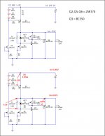
I want use shal shunt for my DAC, out put +5v and -5v, but In my contry I dont fine 2SK170 and Bc550 in you cricuit Q2, Q5, Q6 = 2SK170, Q3 = BC550.
Aloso What transitor I can replaced 22SK170 and BC550???
Can you show for mee. Thank you very much
Dia thien thai
Best regarder
You can see in my cricuit
Attachments
Hi there dia thien, since it involves v1 perhaps you should listen to what salas will say when he wakes up 😀
As a replacement for 2sk170 , can you find 2n3819 in your part of the world? If not, any n-channel jfet with an Idss of 6-10 mA can be made to work. As a replacement for bc550c, can you find 2n5088, or 2n4401? Ask your local electronics store for an NPN transistor with higher gain. That would be what I would try.
As a replacement for 2sk170 , can you find 2n3819 in your part of the world? If not, any n-channel jfet with an Idss of 6-10 mA can be made to work. As a replacement for bc550c, can you find 2n5088, or 2n4401? Ask your local electronics store for an NPN transistor with higher gain. That would be what I would try.
It is said not to use a capacitor at the output of a shuntregulator,what if the amp pcb,preamp pcb or similar contains elyts on the positive and negative rails to earth,should they be removed?
Hi Salas and Ikoflexer !
I want use shal shunt for my DAC, out put +5v and -5v, but In my contry I dont fine 2SK170 and Bc550 in you cricuit Q2, Q5, Q6 = 2SK170, Q3 = BC550.
Aloso What transitor I can replaced 22SK170 and BC550???
Can you show for mee. Thank you very much
Dia thien thai
Best regarder
You can see in my cricuit
Don't do it. To use a higher pinch off than -0.5V that the 2SK170 provides, takes to lift the Vbe margin with a resistor under the BC550. That will squeeze the voltage across a lot. The output Mosfet can measure 4V Vgs for instance. Use a transistor shunt.
It is said not to use a capacitor at the output of a shuntregulator,what if the amp pcb,preamp pcb or similar contains elyts on the positive and negative rails to earth,should they be removed?
Those shunts here actually terminate with the recommended output capacitor. Its quality is audible indeed.
If you have further capacitors on the audio circuit PCB, you must see if they are part of local decoupling or R-C filtering before eliminating. If you are to remove some, don't remove the shunt's termination cap. Leave it there and use remote sensing nodes and wiring.
Are there any disadvantages of keeping them there?Will the regulator oschilate with them?If you are to remove some,
Depends on inductance of wire in between and the actual job they do locally and in their ESR. They can help the sound or not, you have to listen with them and without them in the particular configuration you are going to arrive. But oscillation due to capacitors on the main circuit I haven't encountered yet.
For those that built or will build one of these, something to keep in mind. The measured noise with the zener bypassed by a 100uF cap was between 400 and 500uV. With a 4700uF, the noise went down to less than 30uV, however, the inrush current for about 20 seconds was more than 1A. Just saying.
I have put up to 10000uF and I have seen benefits, it depends on the intrinsic noise of the Zener #number and its voltage range (12V ones seemed to be the quitest), but the instant current was too much and led to instabilities. I have settled to 1000uF and xxxxxxA type glass encapsulated Zeners. Which is a good compromise. TC compensated ones are the best but very expensive & not easily available to the diyer in no quantity purchace. As I have seen on FFT, the noise has a pink profile. It usually gives more robust bass subjectively than lowering hiss the better is filtered. Alternatively, LEDs can be used if the Vout asked is low enough to be tackled practically. There, 100-220uF is enough.
Hi Salas,
if i put a gate stopper of 220 ohms in R2, it is correct? Thank you Maxpou
http://www.diyaudio.com/forums/showpost.php?p=1899742&postcount=967
if i put a gate stopper of 220 ohms in R2, it is correct? Thank you Maxpou
http://www.diyaudio.com/forums/showpost.php?p=1899742&postcount=967
Hi Salas,
if i put a gate stopper of 220 ohms in R2, it is correct? Thank you Maxpou
http://www.diyaudio.com/forums/showpost.php?p=1899742&postcount=967
It will work alright. But when able put the 470R because its damping it a bit better in this particular schematic.
Way back in post 745 Salas was kind enough to provide a circuit to power the Vd of my B32s, which several people have built since.
I've delayed building mine (holidays, work, other projects) but will be building mine this week, Colour me cautious, but I'd like to clarify a couple of things before I build it.
So...
In the circuit linked above, Q5 (fed from the LED's in the CCS) should ideally have an Idss of 5-10mA, Q6 (under the zener) an Idss of 4-5mA and Q2 (above the BC550C) should have an Idss of 5-10mA. With the BC550C we are looking for an HFE of 300.
I have sk170bl's for Q5,6 and 2
Hopefully I'm correct in the above, but feel free to correct me.
Now, If I have a different circuit, which requires a different voltage, and draws more current, would I change the above circuit as follows (thinking 15-20V)
Change the resistor R1 in the CCS so that for the voltage drop across the LED's, the new resistor will draw the same current that is required by the load cicuit+20%
Next, change the zener to a represent the voltage required (eg 1N965B for 15V)
And lastly, the Vin should be 5V above the required voltage, and capacitor voltage ratings adjusted to reflect this.
I'd really appreciate confirmation/correction of the above, as it helps me learn!
Cheers!
So...
In the circuit linked above, Q5 (fed from the LED's in the CCS) should ideally have an Idss of 5-10mA, Q6 (under the zener) an Idss of 4-5mA and Q2 (above the BC550C) should have an Idss of 5-10mA. With the BC550C we are looking for an HFE of 300.
Larger HFE will give you a higher loop gain, and thus lower output impedance. I wasn't very careful with the Idss of jfets, used them all in the 6-10mA range, and everything was fine.
Now, If I have a different circuit, which requires a different voltage, and draws more current, would I change the above circuit as follows (thinking 15-20V)
Change the resistor R1 in the CCS so that for the voltage drop across the LED's, the new resistor will draw the same current that is required by the load cicuit+20%
Next, change the zener to a represent the voltage required (eg 1N965B for 15V)
And lastly, the Vin should be 5V above the required voltage, and capacitor voltage ratings adjusted to reflect this.
I'd really appreciate confirmation/correction of the above, as it helps me learn!
Cheers!
Yes on all counts. People try different % current going through the shunt, and set on something that makes sense sonically and/or as far as power dissipation goes. The 20% you mention I'd say is a minimum, to power a preamp. For a power amp, it's a different story. Worth determining the max load current you'll ever have, then top that with some percentage.
Hope this helps. I'm sure salas will have some insightful comments.
10R would give you 200mA. Roughly a 2V drop across it. If you feel that the sinks available get a bit hot, then use a 15R 2-5W R1. That will give you roughly 150mA with most Leds. Measure 2.2-2.3V drop across R1. At such power levels, it is good to run enough current so to keep the Mosfets alive enough for transcoductance. Since you will use some sink, better let it work.😉
Ikoflexer and Salas, many thanks!
The applications I'm thinking of in the future are the analogue stages of the B32s Dac, and also the +/- 15V supply to a Class A headphone amplifier I've built, using the classic topology of the JLH Class A speaker amp. The output transistors are biased to 100mA. I wanted to figure out what to do, RE the shunt, so thanks for confirming that.
I will report back when I get them built!
Great, have fun! Looking forward to hear about your built once it's fired up and running (metaphorically speaking 😀).
I recall seeing a schematic for +- 15 volts versions of the regulators but I can't seem to find them now. Any help would be appreciated!
Have a look at posts 11 and 12 in this thread
http://www.diyaudio.com/forums/showthread.php?postid=1854512#post1854512
All you need is to modify the voltage reference and input voltage. Instead of the string of LEDs you can use a zener diode, and use a 20-25V filtered input.
http://www.diyaudio.com/forums/showthread.php?postid=1854512#post1854512
All you need is to modify the voltage reference and input voltage. Instead of the string of LEDs you can use a zener diode, and use a 20-25V filtered input.
Look there http://www.diyaudio.com/forums/showthread.php?t=145201&page=2
Posts 11&12 have the DCB1's symmetric. Just make R1=10R, Vin=20V, and add a couple of Leds in the Vref. Probably 7 will get you around 15V. That will run at about 200mA. What is the B32's analogue stage current need?
Posts 11&12 have the DCB1's symmetric. Just make R1=10R, Vin=20V, and add a couple of Leds in the Vref. Probably 7 will get you around 15V. That will run at about 200mA. What is the B32's analogue stage current need?
- Status
- Not open for further replies.
- Home
- Amplifiers
- Power Supplies
- The simplistic Salas low voltage shunt regulator