Hi Salas,
I re-edited the schematic according to your guidance (use A1015 and 1R && 0.1u). I added two more led / LM329 on Vref part so I can use it for higher voltage.
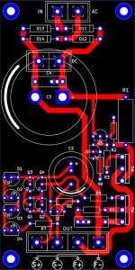
I managed to do a layout based on that schematic, Could you check it to see if it is ok or I'm wrong / missing something.
Thanks!
I re-edited the schematic according to your guidance (use A1015 and 1R && 0.1u). I added two more led / LM329 on Vref part so I can use it for higher voltage.
I managed to do a layout based on that schematic, Could you check it to see if it is ok or I'm wrong / missing something.
Thanks!
Attachments
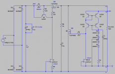
There is a max Vout that the lower mirror BJTs type can take in mW. Usually no more than half its max spec for long term reliability. Check the voltage drops on them so to determine your practical Vout max. You could turn Q1 & Q2 face to face so to can thermally bond them. Not the other two, they will run different mW. Correct connections layout details I can't review as it takes much time.
Many thanks! General layout comments is enough for me. I will correct the layout, do some check and send it to a local PCB company. I'm going to build +-15V version so I think A1015 can withstand these mW. With higher voltage, I can switch them for A970s. I hope it will went well.
Why are D3 and D4 shorted out? Is this just for the option of higher voltage? (probably)Hi Salas,
I re-edited the schematic according to your guidance (use A1015 and 1R && 0.1u). I added two more led / LM329 on Vref part so I can use it for higher voltage.
I managed to do a layout based on that schematic, Could you check it to see if it is ok or I'm wrong / missing something.
Thanks!
Also, lower noise from the current mirror would be had with some emitter ballasting---but perhaps the voltage references are already dominating enough for this to have a significant effect.
Are you referring to the dissipation of Q3? If the loop is closed it sees only the SK117 current of 3.5mA, right? Even with 15V across that's only 53mW, actually less because of the gate-source voltage of the DMOS part. The SA1015 parts are rated for 400mW I believe at a 25C ambient.There is a max Vout that the lower mirror BJTs type can take in mW. Usually no more than half its max spec for long term reliability. Check the voltage drops on them so to determine your practical Vout max. You could turn Q1 & Q2 face to face so to can thermally bond them. Not the other two, they will run different mW. Correct connections layout details I can't review as it takes much time.
Yes, I refer to Q3 that will see Vce=Vo-VGSM2 thus DisQ3=Vce*Iq. The other BJTs will only drop under a Volt each.
Since he mentioned more LM329s capability, there will be an eventual Q3 dissipation limit to keep in mind. Constant dis. for boxed conditions near sinks etc.
Since he mentioned more LM329s capability, there will be an eventual Q3 dissipation limit to keep in mind. Constant dis. for boxed conditions near sinks etc.
One could also put some resistance in series with the Q3 collector to share some of the dissipation, bypassing with a small C to make the resistor's effects go away at high frequencies.Yes, I refer to Q3 that will see Vce=Vo-VGSM2 thus DisQ3=Vce*Iq. The other BJTs will only drop under a Volt each.
Since he mentioned more LM329s capability, there will be an eventual Q3 dissipation limit to keep in mind. Constant dis. for boxed conditions near sinks etc.
If no bigger form factor low Rbb BJT was available, and high Vo was planned, maybe a solution to try, yes. But it can detract from the open loop gain phase margin.
In general, up to 1/3 the Ta=25 max dissipation spec will be reliable in real life conditions of constant dissipation in a closed box ambient.
In general, up to 1/3 the Ta=25 max dissipation spec will be reliable in real life conditions of constant dissipation in a closed box ambient.
Assuming you do not imply a lineair PS.Hi Salas
Can I use one CCS to feed two different voltage regs ?
Imagine a BiB with two different output mosfets and corresponding error voltage circuitry sharing the same input CCS..... is it possible ?
You can do it in series,
so stack a 5V shunt and 10V shunt and you have (+/-) 5V and (+/-) 15V
not in parallel of course, then you would only have (-) 5V.
I use the parentheses because the earth point can be at any node of this series stack. So with these two shunts and one CCS:
- +15, +5; or +15, +10; with the earth at the bottom
- +5, -10; +10, -5 with the earth in between
- -5, -15; -10, -15 with the earth at the top
Has anyone had tried miniaturize the Salas Reflektor circuit (or any of the Salas circuits)? I built 4 of the version 1.2R to power a class A headphone amp and they are superb. But they are quite big and run hot. Now I need to build some shunts for a DAC with very small current demand.
Paul Hynes and Tent labs offer miniaturized shunt regs barely bigger than a typical 7805. Looking at the Reflektor circuit most components are available surface mount and could be small. But the IRF9610 and MTP3055 are big and I'm not so sure they would perform well passing just a few mA.
I need shunts for a DAC I am building needing 6 x 5v supplies with current consumption per supply around 10-40mA dependent on supply (it is actually a DIY DAC board I am fitting in a commercial CD player, so space is limited). I could build 6 std Reflektors but that would need quite a transformer and a lot of space and generate a lot of heat. And I want separate regulators per supply.
So has anyone replaced IRF9610 and MTP3055 with smaller, maybe SOT-23 devices to produce a much smaller reg for low mA applications? Or any recommendations?
I have in mind to add a DC input only small size Reflektor-D board with the Mosfets bolting to the side or down to external surfaces. About SOT-223 that can be logic level I will have to look. There are some. But this will be really low mA without sinks. It must be a separate lower spec thing.
Salas, if using DC input (no need to take AC-variation in consideration), then approx how much would you want/need to drop over the Reflektor-D and SSLV1.1?
The CCS must be driven such that it actually behaves as a CCS.
This requires that the CCS drops some voltage.
This is the biggest difference between a Series regulator and a Shunt regulator. The necessary volts drop across the CCS to make it perform.
This requires that the CCS drops some voltage.
This is the biggest difference between a Series regulator and a Shunt regulator. The necessary volts drop across the CCS to make it perform.
More than Vgs. 5V for the Ciss to level off enough. It can be made with a BJT too. But to see ripple passing in a bib or reflektor you need go down to 1.7V in-out.
it's not the irf9610 alone.
It's the CCS of which the irf is just a part.
The three (or sometimes 4) LEDs drop a voltage of 5 to 7V.
If you drop just this and no more, then the CCS action is not very constant.
The Shunt part then has to work harder to compensate for the variable current passing the CCS.
5V of LEDs seems to work if Vin - Vout >7V (for 3 LEDs)
For 4LEDs I'd guess one would need to aim for >9V of drop.
They drop it to ground not across the reg. So its not a series requirement, has to do with the lowest good Vin. That connects tighter to the Vout relation as you go to lowest allowed. It's more specific to the bib Leds number which was designed mostly for analog stuff higher rails, the reflektor uses a BJT for CCS control so not to be that dissipative a CCS for low Vout. That is why I say 1.7V series drop will show ripple. 5.5Vo lowest recommended for Bib + 1.7=7.2 to gnd. A bit of a drop in the mains and it goes off CCS full draw. In the Ref-D even two Volt series drop also goes but its not for good performance. 5V are good. Ultimately Vin to gnd has to at least contain M1 Vgs, one Vbe, and 2xJ1 Vgs.
Sorry, I didn't just mean just SOT23, also SOT89 or any other surface mount package.
I feed all my regs with a DC supply so this does make the regulator fairly small without the need for rectification and smoothing. But when I look at the specs of the CCS and shunt transistor they are usually quoted at several amps and in the build manual the lowest CCS current is 300mA. I need maybe 40-50mA CCS with maximum of maybe 100mA for 1 circuit. I'm not sure the current RefleKtor circuit will like such low currents. I can build it and play around but I notice in the threads that it took a while to arrive at the MTP3055 and my knowledge isn't sufficient for me to inherently know what parameters will make a new, surface mount, device work well.
I feed all my regs with a DC supply so this does make the regulator fairly small without the need for rectification and smoothing. But when I look at the specs of the CCS and shunt transistor they are usually quoted at several amps and in the build manual the lowest CCS current is 300mA. I need maybe 40-50mA CCS with maximum of maybe 100mA for 1 circuit. I'm not sure the current RefleKtor circuit will like such low currents. I can build it and play around but I notice in the threads that it took a while to arrive at the MTP3055 and my knowledge isn't sufficient for me to inherently know what parameters will make a new, surface mount, device work well.
- Status
- Not open for further replies.
- Home
- Amplifiers
- Power Supplies
- The simplistic Salas low voltage shunt regulator