I raised this issue way back when remote sensing was first suggested. I was told to take my concerns elsewhere.How long are the force and sense wires? I suspect they might be acting as antennae.
Today I set up another shunt (BiB Clone) that is known for stability and I get the same measurements, so I rest assured it is due to my measurement setup.
Sense and force wires are 5cm long each and not torsioned together.
BTW, both measured shunts have allready been tested powering sensitive amps (Folded) and they both sound perfect..... V12R as a much larger soundtsge presentation and the highs are sublime.
BiB has a somehow nicer bass with more presence 🙂
I had the CFP BJT (Q6) closest possible to the output MOSFET. At least in the second attempt. There I tried TO-220 too and it worked. IRF9530 for Crss is just a little slower and it should work OK.
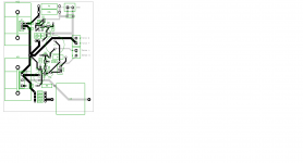
RC, a suggestion that may/not suit your design method
If you exchange positions of the big C3 with the R13s and shorten the long track by running it around the back of the Q5 heatsink pins, this will allow mire freedom to move the C2 out of the way and shift that Q6 closer to Q5
A bit more over-the-top maybe - add a simply CMx to the input if stretching the pcb is okay - a total package, if you get what I mean.
Another not so easy one - separate the heatsinks a bit more and fit the 'force +/G' terminals there - they don't have to be grouped with the sense terminal at all - will probably need to move the input power terminals too, for shorter Ground tracking
Could move the sense terminals lower to reduce tracking from 'sense G' to Q10 and the 'sense +' to Q8 maybe too ..
my Sunday 2 cents ....
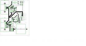
Can not move C2 away from Q5. In fact it is already too far away.
This cap is fundamental to avoid oscilations and it should sit on top of Q5.
I will try to move Sense connector to a lower position.
Yesterday "late night" I decided to remove C2 and got steady oscilations around 5Mhz.
Then I connected a 10u film instead and the oscilations reduced in amplitude just slightly.
Sorry, what about shifting it to underneath and have it lay on it's side - this will allow almost direct pin connection to Q5 and also allow you to change the connection between Q6 and Q5, via R7, etc - makes use of both sides of the board and normal pcb standoffs are about same height
Or move it to the backside of the heatsink, right between the fins of the heatsink itself, and maybe use a transistor clip instead of the usual bolt/nut for fastening the Q5 to the haetsink to assist assembly
A bit 'outside the square', I know ...
Or move it to the backside of the heatsink, right between the fins of the heatsink itself, and maybe use a transistor clip instead of the usual bolt/nut for fastening the Q5 to the haetsink to assist assembly
A bit 'outside the square', I know ...
Layout version 4
BTW: I was experimenting with different output caps while the shunt was working.... connected a 10u film to the output and there was a small spark.... now the shunt does not regulate... I have 0.2v at Q7 base instead of the usual 0.7v.... any hint on what was burned ?
BTW: I was experimenting with different output caps while the shunt was working.... connected a 10u film to the output and there was a small spark.... now the shunt does not regulate... I have 0.2v at Q7 base instead of the usual 0.7v.... any hint on what was burned ?
Attachments
Good news.....
I have another V12R build working and just replaced the 47u EL by a 10u film on the output (without zobel resistor) and it works.... it does regulate and I can not see steady strong oscilations as I saw yesterday with just the 4u7 film and 0.25ohm resistor in series.
So I believe it can be done with only one film cap in the output.
Just found the origin of my initial High freq readings..... my bench is illuminated with a high power lamp (200w) and I use an electronic dimmer..... when I switch it off, all nasties go away 🙂
"I would not use R13 at all if not using C2" 😉 #6821Good news.....
I have another V12R build working and just replaced the 47u EL by a 10u film on the output (without zobel resistor) and it works.... it does regulate and I can not see steady strong oscilations as I saw yesterday with just the 4u7 film and 0.25ohm resistor in series.
So I believe it can be done with only one film cap in the output.
Just found the origin of my initial High freq readings..... my bench is illuminated with a high power lamp (200w) and I use an electronic dimmer..... when I switch it off, all nasties go away 🙂
Darkness can sometimes "illuminate" the solution to a problem.😀
BTW: I was experimenting with different output caps while the shunt was working.... connected a 10u film to the output and there was a small spark.... now the shunt does not regulate... I have 0.2v at Q7 base instead of the usual 0.7v.... any hint on what was burned ?
The error amp BJT and possibly its nested JFET can be hit when a "live" mod mishandling happens especially when over 25V output level.
"I would not use R13 at all if not using C2" 😉 #6821
Why do you use R13 when using both C2 47u AND C3 4.7u ?
Thank you so much..... you made it simple for me to recover this one 🙂The error amp BJT and possibly its nested JFET can be hit when a "live" mod mishandling happens especially when over 25V output level.
Those are pernicious sources of interference. Good detective work!Just found the origin of my initial High freq readings..... my bench is illuminated with a high power lamp (200w) and I use an electronic dimmer..... when I switch it off, all nasties go away 🙂
Why do you use R13 when using both C2 47u AND C3 4.7u ?
Thank you so much..... you made it simple for me to recover this one 🙂
The OLG phase margin gets different with the 47u and then the R13 is helpful in tailing off the curve better. If using a film only, better alone. Closer to danger zone but it can work on some loads (like yours). Oscilloscope is your friend in particular layouts, loads, and decisions. As always.
Those are pernicious sources of interference. Good detective work!
BTW. *Forgot to mention I had also used LM329 (1 or more) instead of Norton Ref or LEDS but with 470uF electrolytic filter across.
Troubleshooting woes
Hi Salas, I've been reading this thread for sometime and decided to build four Salas shunt regulators based on version V1.2R.
Only one of the four regulators is working. I have two +38Vdc in +24Vdc out regulators and two -38Vdc in -24Vdc out regulators.
I have them all connected to 1Kohm dummy loads for testing. Below is a summary fo what each reg is doing:
Have you had similar problems when building? is there any indication to which part of the circuit is causing the above. I have checked solder joints and component orientation as well as replacing specific components like the LSK170 and 2N5457 in case I static fried them but had no luck.
Any help would be appreciated.
Thanks
Dom
Hi Salas, I've been reading this thread for sometime and decided to build four Salas shunt regulators based on version V1.2R.
Only one of the four regulators is working. I have two +38Vdc in +24Vdc out regulators and two -38Vdc in -24Vdc out regulators.
I have them all connected to 1Kohm dummy loads for testing. Below is a summary fo what each reg is doing:
- Reg 1 (+):
- working perfectly 🙂
- Reg 2 (+):
- LED is on and output is +37.8V but altering the variable resistor R112 does nothing to the output it remains at +37.8V.
- Reg 3 (-):
- LED is on and output is -10.7V but altering the variable resistor R212 does nothing to the output it remains at -10.7V.
- Reg 4 (-):
- LED is on and output is -10.7V but altering the variable resistor R212 does nothing to the output it remains at -10.7V.
Have you had similar problems when building? is there any indication to which part of the circuit is causing the above. I have checked solder joints and component orientation as well as replacing specific components like the LSK170 and 2N5457 in case I static fried them but had no luck.
Any help would be appreciated.
Thanks
Dom
Attachments
Check Q106 and Q109 on the positive shunt...... never built negative shunts and all my V12r worked from the start.
PS: The one that got away is now alive and kicking.... can confirm that using IRF9530 is a good option instead of the 9240 or 9140 🙂
PS: The one that got away is now alive and kicking.... can confirm that using IRF9530 is a good option instead of the 9240 or 9140 🙂
I would check the working one's everything Vbe and Vgs against its analogous non working one to troubleshoot. Also add the zener + resistor starter. Maybe just a kickstart issue. Why C102 103 202 203 are 4.7uF instead of 47uF BTW? Just a schematic designation error?
- Status
- Not open for further replies.
- Home
- Amplifiers
- Power Supplies
- The simplistic Salas low voltage shunt regulator