Post5019
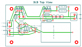
Now reduce the loop area of the main current flow route.
Squeeze the sense lines as close as possible (low loop area).
Now reduce the loop area of the main current flow route.
Squeeze the sense lines as close as possible (low loop area).
Now really tight (as p2p goes).
PS: Does anyone know this supplier ? outillage.e44.com
E44-Eurocard motif centronix/sub-d - 100x160mm - fr4 (1pc/bl) à 5,00 ?[productImages]/0/
PS: Does anyone know this supplier ? outillage.e44.com
E44-Eurocard motif centronix/sub-d - 100x160mm - fr4 (1pc/bl) à 5,00 ?[productImages]/0/
Attachments
Hello there
Im noob here
Please advice....
Im currently building a CMoy with salas shunt reg for PSU
I've got the board from CRT ( thank to him )
But when i done soldering, it didnt worked well....
Im using transformer 50vac, 2x15v
And im using MSR860 diode, resistor 10R 5 watt
I only got 9.7v from V-
But V+ is zero....
Please advice....
No, I am not right.
I am asking Salas, where should the cap C3 be?
Nearest to the Mosfet depending on how much heat is being dissipated. If its a high dissipation setting better compromise distance.
But when i done soldering, it didnt worked well....
Im using transformer 50vac, 2x15v
And im using MSR860 diode, resistor 10R 5 watt
I only got 9.7v from V-
But V+ is zero....
Please advice....
I see a bunch of voltage reference leds not emitting. See if you got one or more of them wrongly orientated or dead from too hot an iron or long soldering. If your meter can light an led in diode mode just test them one by one with same and correct in circuit polarity without removing them first. If meter can't, use a 9V battery fast.
What are the news of the made in Japan low voltage mod Reflektor? Worked stable in the end for all there? Did it bring goodness to music? I encourage our Japanese friends to write their story here too, and show some pictures if they have also.
Need Information Please
Dear Salas,
I want to build your shunt regulator with this schematic for +5V output for my DAC
I use PCM1798 and CS8416.
Can this regulator maintain +5V on its output as PCM1798 and CS8416 greatly vary in current requirement as the sampling frequency change?
For 44.1KHz, PCM1798 require about 25mA, CS8416 require about 14.5mA.
For 192Khz, PCM1798 require about 45mA, CS8416 require about 40.5mA.
I usually play different sampling rate music files with my DAC.
Best Regards
Dear Salas,
I want to build your shunt regulator with this schematic for +5V output for my DAC
An externally hosted image should be here but it was not working when we last tested it.
I use PCM1798 and CS8416.
Can this regulator maintain +5V on its output as PCM1798 and CS8416 greatly vary in current requirement as the sampling frequency change?
For 44.1KHz, PCM1798 require about 25mA, CS8416 require about 14.5mA.
For 192Khz, PCM1798 require about 45mA, CS8416 require about 40.5mA.
I usually play different sampling rate music files with my DAC.
Best Regards
Everyone,
Did anyone ever built a SMD version of the SSLV?
What about:
- Component choices (MOSFETS, resistors, caps)
- Layout considerations
I would very much like to learn from others before building....
thanks
Did anyone ever built a SMD version of the SSLV?
What about:
- Component choices (MOSFETS, resistors, caps)
- Layout considerations
I would very much like to learn from others before building....
thanks
These shunt regulators dissipate a lot of heat.
There is no space/volume advantage to using smd.
Why complicate the assembly by introducing leadless components?
There is no space/volume advantage to using smd.
Why complicate the assembly by introducing leadless components?
True, i was actually thinking to use smd versions of the resistors and the leds, and indeed leave the rest in peace.
Just wondering if anyone succeeded so far, and see what pitfalls there are in layouting
I actually find smd more pleasant to work with than trough hole as well
Just wondering if anyone succeeded so far, and see what pitfalls there are in layouting
I actually find smd more pleasant to work with than trough hole as well
if you find smd more practical, i d place a bc849c/59c wherever i can and bf862 as the ccs for reference voltage (though bf862 here might hurt output z too much in the 1.1) .the effect of their low noise could be heard and they are cheap.
Last edited:
Ricardo, BiB guide Rev 2 said: "There is no need for strict matching, use your lower ones from the 3-5mA subgroup for Q102,202,302, your medium ones for Q103,203,303, and your stronger ones for Q105,205,305."
It's a pleasure to help you, will be better if you use near 3mA for Qx02, near 4mA for Qx03 & near 5mA for Qx05, if you don't have them sent me a pm to see if I can help you.
This must have been asked before, but i cant find it (not at least in a way that i understand).
Can somebody explain the function of the zobel network at the output of the 1.2bib? What happens if i use different capacitor values (i now use 220uf + 3.3uf, where 4.7-10uf is recommended).
Thanks!
Can somebody explain the function of the zobel network at the output of the 1.2bib? What happens if i use different capacitor values (i now use 220uf + 3.3uf, where 4.7-10uf is recommended).
Thanks!
Did i read correctly in the thread that for powering a tda1541a with the ssr1.1, a 220uf lytic is recommended as output cap? Why is this preferred over a mkt+r in this particular case?
In the same post by salas i read even a 1000uf was recommended for clocks! Why?
In the same post by salas i read even a 1000uf was recommended for clocks! Why?
- Status
- Not open for further replies.
- Home
- Amplifiers
- Power Supplies
- The simplistic Salas low voltage shunt regulator