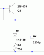
Great noise specs. Thank you!That one is with 2200uF Vref cap. Better for clock.
Theoretical. But it certainly has low noise BJTs and medium gain, so should be OK for a Mosfet follower noise class.
Thanks for pointing this out. I was also calculating that with Led I can't get lower then ~6.5V.P.S. Won't go lower Vo than Vgs+2Vbe+Led Vf mind you.
Edit: This arrangement seems OK for Vo=5V, and that's it. No lower no Led.
Btw... I hope practically I could get it ~50 nV/SqrrtHz
Last edited:
For a clock you want lower impedance at high frequency. Noise is less important.
There are arguments that low flicker noise at 1-10Hz is a highly desirable spec for supplying clocks?
Thanks for pointing this out. I was also calculating that with Led I can't get lower then ~6.5V.
Btw... I hope practically I could get it ~50 nV/SqrrtHz
Yes, the models are not very accomplished for such predictions. On the other hand I have seen people juxtaposing LTSPICE noise analysis with results in phono preamps claiming a good match. Not sure, I lack lab analyzers to confirm. Especially VLF 1/f values.
Hi Salas
I am planning to build a bench psu that should be able to work from 10v to 40Vout.
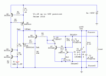
The schematic should be the one below.
I am planning to add a resistor circuit (instead of the trimmer) as per Andrew´s sugestion. How low should this Trimmer equivalent resistance be to get 40Vout ? ( I presume that the higher the resistance, the lower the Vout)
Attachments
Last edited:
Ricardo to be able to work from 10-40Vout you have to change the Vin accordingly, difference Vin-Vout 10VDC.
Hi Salas
I am planning to build a bench psu that should be able to work from 10v to 40Vout.
The schematic should be the one below.
I am planning to add a resistor circuit (instead of the trimmer) as per Andrew´s sugestion. How low should this Trimmer equivalent resistance be to get 40Vout ? ( I presume that the higher the resistance, the lower the Vout)
Depends on IDSS of each K170. You got to test a range of resistors for given IDSS. But I would not use a CCSed shunt for bench supply. Because you would need to change CCS current ceiling also to be really flexible, and there will be heat when covering the low region when the trafo should cover the high region too. Due to some extra current allowance.
I will use a TX with several taps. It can output 20V to get 10Vout, 30V to get 20Vout, 40V to get 30Vout and 50V to get 40vout.
I will use 7,4mA Idss for the Vref CCS jfet.
That is not an issue. What I need to know is the lowest Trimmer value to get 40 Vout.
I know that output voltage = VbeQ7 + [IdQ9 * R11] + [IbQ7 * R10] but I do not know VbeQ7, IdQ9 and IbQ7.
In this case we control Vout by modifying IdQ9 that lowers with increased Trimmer value. That is ok if I use only one 1K trimmer, but if I want to use Andrews resistor layout (including a series resistor to the trimmer) I must know what are the limits.
To get lower Vout, there is no problem, but to increase Vout, there must be a ceiling for the lowest trimmer value.
Last edited:
Create a 0.6V source (maybe a battery, 100R, and a diode), connect your particular K170 across the diode. Use 1k trimmer between GS connected as in the schematic you posted. Note the value that will give you 0.83mA. Use that as your smallest resistor for a ~40V ceiling when in the actual circuit.
I opted to use one single 1k trimmer as per your design in order to do not loose fine adjustment possibility.
Now I have one issue: I am using R11 = 30k1 and the lowest possible voltage I get is 10.8 V. I get this voltage with the trimmer set to 0 ohm so I can not go lower.
I do not have anymore trimmers... can I get R11 to 27k so I can adjust to 10Vout, without compromising performance ?
Now I have one issue: I am using R11 = 30k1 and the lowest possible voltage I get is 10.8 V. I get this voltage with the trimmer set to 0 ohm so I can not go lower.
I do not have anymore trimmers... can I get R11 to 27k so I can adjust to 10Vout, without compromising performance ?
Probably when set to 1k. Yes 27k, especially if you use a bit bigger capacitor across the voltage reference.
Correction:
The trimmer is 1k so I can not reduce voltage further.
I plan to use 10u MKP.. with 27kr for Vref ... What can I expect if I do not increase this cap value ? More noise than with 30kr? I reduced this R11 from 47k to 30k so I could fine tune the Vout with more precision.
Now I have one issue: I am using R11 = 30k1 and the lowest possible voltage I get is 10.8 V. I get this voltage with the trimmer set to 1000 ohm so I can not go lower.
The trimmer is 1k so I can not reduce voltage further.
I plan to use 10u MKP.. with 27kr for Vref ... What can I expect if I do not increase this cap value ? More noise than with 30kr? I reduced this R11 from 47k to 30k so I could fine tune the Vout with more precision.
Last edited:
Ok... I will not reduce R11 anymore.
I will replace the 1k trimmer by a fixed 1k8 Kiwame // 10k trimmer.
I will replace the 1k trimmer by a fixed 1k8 Kiwame // 10k trimmer.
Reflektor
Hi,
With a lot of help from Salas, I have just built myself a 18v Reflektor. Now powering a DAC and let it run in a bit before listening. First impression is not bad at all 🙂...
Hi,
With a lot of help from Salas, I have just built myself a 18v Reflektor. Now powering a DAC and let it run in a bit before listening. First impression is not bad at all 🙂...
- Status
- Not open for further replies.
- Home
- Amplifiers
- Power Supplies
- The simplistic Salas low voltage shunt regulator

