Hi Andrew
Reading a thread about pedja´s buffer, I read your post " even those that design and build discrete regulators sometimes use two positive regulators rather than design a + & - pair.
The only down side to this twin positive regulator is the requirement for dual secondaries and dual bridge rectifiers.
Most will accept the extra cost because of the technical benefit accruing from +ve regulators."
Do you also recommend the use of two positive Salas regs if we use separated secondary windings in the TX ?
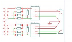
If you used the schematic like I posted you would not need separated transformer windings. The CCS is only seen as another load by the regulator, it shouldn't matter much, if that is the only change - however I would like corroboration with Salas on this.
Salas, I sent you an email. I thought you were on vacation but I can't find the post anymore? If so, sorry to bug you.
- keantoken
Numbers are going down fast, from 120mOhm to 28 already. Now if you used a much higher hfe 560C instead of 2N4403 as error amp and a CCS instead of its resistor load plus 4 wires connection like we usually do, things could go even better? We just stick an LED between the ref resistor and its CCS for drift, the diode at the emitter worsens performance. Just Use a JFET that has <0.6V pinch off, and you won't need an extra silicon junction drop, vbe will suffice.
Hi and welcome back,
after the inputs from ikoflexer and keantoken and of course yourself I went back and re-read the Jung articles, scratched my head a lot, simulated, and changed the measurement setup. I will hopefully perform a few more measurements next week, time permitting, (due to go on an island myself next week ;-) most of the noise was really due to my bad setup. learning.....
as for your suggestions, that sounds very good. I now have the experrimental basis to try out the changes and will report back, and I guess I will have to (read: want to ) redo the shunt regs in my phono preamp again....
If you used the schematic like I posted you would not need separated transformer windings. The CCS is only seen as another load by the regulator, it shouldn't matter much, if that is the only change - however I would like corroboration with Salas on this.
Salas, I sent you an email. I thought you were on vacation but I can't find the post anymore? If so, sorry to bug you.
Hi keantoken
Would you please point me to your schematic ?
I am planning to build a line stage preamp (pot + buffer) powered by two positive SSLV V1 that I have already built.
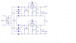
I also have a two winding TX so I would like to do something like this but using SSLV instead of the 338 regs:
Attachments
Hello Merlin, thanks for your reply, just a last question: it is R1 that adjusts current right?? which value should i use for 500mA?I use this for BII, only change Vin-Vout 7-10V difference target Vout, R12 use 1K trimmer for 5.5Vout, you can get better perfomance using more current: I use ca. 500mA🙂
Enjoy
P.S. AndrewT don't be so rude, the thread is too long.
Start with 3R9, possible needs less but first measure voltage accross the resistor to know current.
Hi keantoken
Would you please point me to your schematic ?
I am planning to build a line stage preamp (pot + buffer) powered by two positive SSLV V1 that I have already built.
I also have a two winding TX so I would like to do something like this but using SSLV instead of the 338 regs:
Salas
Can I do it ?
Here is my schematic:
http://www.diyaudio.com/forums/powe...w-voltage-shunt-regulator-84.html#post2667734
- keantoken
http://www.diyaudio.com/forums/powe...w-voltage-shunt-regulator-84.html#post2667734
- keantoken
you have swapped -ve & +ve relative to my comments and my previous posts.... I read your post " even those that design and build discrete regulators sometimes use two positive regulators rather than design a + & - pair.
The only down side to this twin positive regulator is the requirement for dual secondaries and dual bridge rectifiers.
Most will accept the extra cost because of the technical benefit accruing from +ve regulators."
Do you also recommend the use of two positive Salas regs if we use separated secondary windings in the TX ?
None of the 50 or so transfomers I have bought in the last few decades were centre tapped. All were dual secondary.
The only extra cost to using dual -ve Salas Shunt regulators is one bridge rectifier. All else are either the same or cheaper.
Last edited:
Hi Andrew
I have not swapped, just quoting: http://www.diyaudio.com/forums/power-supplies/134464-why-they-building-15v-regs.html#post1680881
I know that in your previous post in this thread you considered using two negative SSLV so I decided to bring this up again because of your post in the thread "Why are they building -15v regs " http://www.diyaudio.com/forums/power-supplies/134464-why-they-building-15v-regs.html#post1678576
I am now finishing the PSU and report latter 🙂
Last edited:
Thank you keantoken
Now I understand ... You are suggesting a positive + negative shunt to use with a single secondary TX.
Maybe I need to try that also, but I have two V1 positive already built and a twin secondary TX.
In the bench, the two +15v shunts already produce -15v ~ +15v acording to plan.... let us see if it works when I replace the dummy load by the actual buffers 🙂
Sorry, I didn't recognise that as a quote taken out of context.
I still stand by the statement that we don't need to make different PCBs for +ve & -ve regulators. This will save money.
I also still stand by the statement that -ve regulators cost less than +ve regulators and that I believe the -ve regulators are likely to perform better than the +ve regs due to the avoidance of any and all Pchannel FETs.
Hi all!
Is this board share the same circuit from Salas low voltage shunt regulator?
Salas low shunt regulator V1.0 - Quanghao.com
Will Salas low voltage shunt regulator work well with Welborne Labs CATO?
Welborne Labs CATO Vacuumt Tube Linestage
Thanks!
Is this board share the same circuit from Salas low voltage shunt regulator?
Salas low shunt regulator V1.0 - Quanghao.com
Will Salas low voltage shunt regulator work well with Welborne Labs CATO?
Welborne Labs CATO Vacuumt Tube Linestage
Thanks!
Where can I get a pcb for the Salas shunt regulator?
I'm looking to build a 12V supply to replace the 7812 chip in an old Quad FM4 tuner (it won't fit inside tuner box I know).
I'm using a LM317 at present fed with a CLC arrangement. Sounds good but maybe not as good as it could.
Best wishes,
Chris
I'm looking to build a 12V supply to replace the 7812 chip in an old Quad FM4 tuner (it won't fit inside tuner box I know).
I'm using a LM317 at present fed with a CLC arrangement. Sounds good but maybe not as good as it could.
Best wishes,
Chris
Hi all!
Is this board share the same circuit from Salas low voltage shunt regulator?
Salas low shunt regulator V1.0 - Quanghao.com
Will Salas low voltage shunt regulator work well with Welborne Labs CATO?
Welborne Labs CATO Vacuumt Tube Linestage
Thanks!
Where can I get a pcb for the Salas shunt regulator?
I'm looking to build a 12V supply to replace the 7812 chip in an old Quad FM4 tuner (it won't fit inside tuner box I know).
I'm using a LM317 at present fed with a CLC arrangement. Sounds good but maybe not as good as it could.
Best wishes,
Chris
For low voltage there is the SSLV1.1 Back In Black PCB. Build thread. Member Tea-Bag has a list for late comers, after the group buy got over, due to further demand. Check his signature link. There is a PDF guide hotfile download link on post#1 of the build thread. Read it.
Many thanks Salas.
The RC filter I'm using at present consists of 4700uF caps and four one ohm resistors in parallel in the form of C-R-C-R-C. The sound was somewhat veiled and murky until I connected an inductor across the second set of resitors which caused the sound to be much more open. Any thoughts? I don't have a value for the inductors but they are probably about 10mH.
Chris
- Status
- Not open for further replies.
- Home
- Amplifiers
- Power Supplies
- The simplistic Salas low voltage shunt regulator

