I'm pretty sure that he used a 100 ohm resistor with a 100uF cap in parallel.
For one of my load tests I used an IRFP240 biased into class A with the AP driving the gate. (I think this is the Dieckman circuit). I also have a Jensen transformer which will take about 300mA DC before it distorts -- same one that AP shows in their PSRR test setup. Last is the WJ circuit. It's probably a good idea to compare all 3 for a reality check.
This is straying from the topic a bit, I recognize.
I think it is on topic. It's important to know how we can measure these regulators, after we build them and have such high expectations, performance wise.
I did the same with a power mosfet in class A as load. I measured the RMS voltage and current with a Fluke 8050A. I suppose I could also use a power precision resistor and measure the voltage across it with my Fluke 8920A.
I did the same with a power mosfet in class A as load. I measured the RMS voltage and current with a Fluke 8050A. I suppose I could also use a power precision resistor and measure the voltage across it with my Fluke 8920A.
I can measure 10uV DC to 1MHz, if you can send me a built one. ;D
I expect a 4-wire connection would be mandatory.
- keantoken
I expect a 4-wire connection would be mandatory.
- keantoken
I can measure 10uV DC to 1MHz, if you can send me a built one. ;D
I expect a 4-wire connection would be mandatory.
- keantoken
Maybe you mean 10 uV AC! Well, my 60dB low noise preamp helps me measure below 1uV AC. But we're talking about output impedance here. I haven't measured yet an output impedance so low on any of these regulators.
Nope, 10uV DC, on the scope. So if I test the regulator with a load of 10mA, I can measure an impedance of 1mR. 100mA, 100uR. I can measure this up to 1MHz. Maybe still could with my voltmeter, but I think it only has a BW of 50KHz (or maybe 500KHz, I don't remember).
- keantoken
- keantoken
Hi guys,
rebuilt another shunt reg (since the other guys are performing their duties in my phono stage) and measured again. This time I put 100uF caps across the LEDs for the current source and the norton ref for the voltage regulator.
First, the setup: I use a MOSFET biased in class A, with a source resistor of 1Ohm and an opamp to compare a DC voltage (coming from a 10 turn pot) to set the DC current, plus an AC voltage to overlay the AC current. This has a capacitor and source follower to couple the AC signal on the load input to a BNC socket.
THen, a soundcard (24bit, 192kHz) to look at the spectrum of that signal. I can reliably measure down to about -90dBu with this setup, not limited by the soundcard but limited by the noise in our lab and the whole construction. This is about 0.23uV.
(It actually works a little better, but there is a lot of 50Hz noise and its harmonics, plus some noise, so I want to be on the safe side). Sorry, no schematic, I have a hand-drawn, smeared piece of paper, this load is built from scrap box parts (maybe one day I'll find some time to properly document....)
Starting up the regulator with 16Vin, 12Vout, CCS set to 200mA, load current 100mA, the first positive surprise is that it is not adding any noise. I can't tell if it adds any noise because with my setup I couldnt detect it.
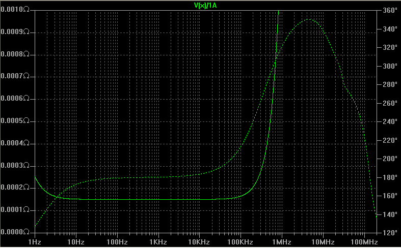
Then, I put a AC current of 27mA @ 1kHz on top, and the output spectrum showed a noise peak of -60dB == 0.8mV. Math gives 28mOhm. Some more work to do, more later.....
(BTW, shorting the diode in the emitter of the PNP yields 3dB improvement...)
rebuilt another shunt reg (since the other guys are performing their duties in my phono stage) and measured again. This time I put 100uF caps across the LEDs for the current source and the norton ref for the voltage regulator.
First, the setup: I use a MOSFET biased in class A, with a source resistor of 1Ohm and an opamp to compare a DC voltage (coming from a 10 turn pot) to set the DC current, plus an AC voltage to overlay the AC current. This has a capacitor and source follower to couple the AC signal on the load input to a BNC socket.
THen, a soundcard (24bit, 192kHz) to look at the spectrum of that signal. I can reliably measure down to about -90dBu with this setup, not limited by the soundcard but limited by the noise in our lab and the whole construction. This is about 0.23uV.
(It actually works a little better, but there is a lot of 50Hz noise and its harmonics, plus some noise, so I want to be on the safe side). Sorry, no schematic, I have a hand-drawn, smeared piece of paper, this load is built from scrap box parts (maybe one day I'll find some time to properly document....)
Starting up the regulator with 16Vin, 12Vout, CCS set to 200mA, load current 100mA, the first positive surprise is that it is not adding any noise. I can't tell if it adds any noise because with my setup I couldnt detect it.
Then, I put a AC current of 27mA @ 1kHz on top, and the output spectrum showed a noise peak of -60dB == 0.8mV. Math gives 28mOhm. Some more work to do, more later.....
(BTW, shorting the diode in the emitter of the PNP yields 3dB improvement...)
I hate to ask, but where is the schematic for this version? I seem to remember the Salas regs having much lower impedance in simulation.
- keantoken
- keantoken
Come on... simulation... reality... do you remember early on, when I was simulating lots of variations, how I got some crazy output impedance results, past 100kHz? I'd like to see one regulator that could do that in reality. At some point I thought mine could... but until I see it measured independently by a few people with similar results, I'll hold my breath. It looks good on paper though... 🙂
I hate to ask, but where is the schematic for this version? I seem to remember the Salas regs having much lower impedance in simulation.
- keantoken
There may be a difference between simulation and actual measurements.
Well there must be a reason, anyway. It would be nice to know, then maybe we could design something better, or at least know when to give up.
Plus nowadays we have better simulation models, for instance from Cordell.
The point for me is to be practical and understand what causes the impedance to be higher than simulated. I would understand if the DC impedance was normal and the AC impedance was much worse than simulated, but if the DC impedance is much worse, it would indicate a modeling/simulation failure.
PS, Iko, what about those Ikoshunt prototypes you were going to send me?
- keantoken
I know what you mean, kt. I don't know what circuit hesener built, but there's a big difference between 28 mOhm and less than 200 uOhm, like my reg simulated a while ago
http://www.diyaudio.com/forums/powe...e-shunt-voltage-regulator-79.html#post2094986
kt, I never built another prototype, as I dropped that project completely. If I build another pcb I'll make duplicates and send you for sure. Sorry about that, too many things on my hands in the last year.
IMHO, without sense/force wires, and without a really good pcb layout, there won't be a low output impedance anywhere close to what the design can do. And no, I don't think my reg could get to 200 uOhm zout in reality.
Hi guys,
rebuilt another shunt reg (since the other guys are performing their duties in my phono stage) and measured again. This time I put 100uF caps across the LEDs for the current source and the norton ref for the voltage regulator.
First, the setup: I use a MOSFET biased in class A, with a source resistor of 1Ohm and an opamp to compare a DC voltage (coming from a 10 turn pot) to set the DC current, plus an AC voltage to overlay the AC current. This has a capacitor and source follower to couple the AC signal on the load input to a BNC socket.
THen, a soundcard (24bit, 192kHz) to look at the spectrum of that signal. I can reliably measure down to about -90dBu with this setup, not limited by the soundcard but limited by the noise in our lab and the whole construction. This is about 0.23uV.
(It actually works a little better, but there is a lot of 50Hz noise and its harmonics, plus some noise, so I want to be on the safe side). Sorry, no schematic, I have a hand-drawn, smeared piece of paper, this load is built from scrap box parts (maybe one day I'll find some time to properly document....)
Starting up the regulator with 16Vin, 12Vout, CCS set to 200mA, load current 100mA, the first positive surprise is that it is not adding any noise. I can't tell if it adds any noise because with my setup I couldnt detect it.
Then, I put a AC current of 27mA @ 1kHz on top, and the output spectrum showed a noise peak of -60dB == 0.8mV. Math gives 28mOhm. Some more work to do, more later.....
(BTW, shorting the diode in the emitter of the PNP yields 3dB improvement...)
I'm sorry hesener, but I'm a little bit suspicious of this number. How well is the soundcard calibrated? -- it would have to be really well calibrated for such small numbers to be accurate.
Have you measured the AC current of 27mA while driving the regulator with it?
Yes Sir
Tomorrow I will change the measurement setup to put a load resistor and drive AC like in walt jung's setup, just to see if my load is off....
The shuntreg schematic for this test was the same I posted earlier (sorry I don't have it on hand but it's in this thread)
I'm sorry hesener, but I'm a little bit suspicious of this number. How well is the soundcard calibrated? -- it would have to be really well calibrated for such small numbers to be accurate.
Agree, and I really haven't had a lot of possibility to verify the output. All the tests I did at higher levels indicate that it works correctly. Then it's a point of using the 24bit resolution, I guess. Will play some more with it tomorrow if I find the time.
It's intriguing how difficult it is to accurately measure the performance of this simple circuit...
Basically, what's the error margin on a sub 5mV RMS measurement. There are not very many voltmeters that can do true RMS, first of all, and then there's the issue of accuracy, and calibration. How does your soundcard know that it's not 33mV instead of 1mV? You must have calibrated it by giving it a sine wave of known amplitude and frequency. But how well have you measured that sine wave, with what instrument, and how accurate was it? Yes, it's not easy to measure such low values.
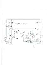
Ah, you must mean this schematic!
http://www.diyaudio.com/forums/powe...w-voltage-shunt-regulator-82.html#post2659413
Likely D1 is there so the circuit won't drift with temperature. You could bypass it with a capacitor, to gain that 3db advantage, though it may have to be a really big one to cover bass.
- keantoken
http://www.diyaudio.com/forums/powe...w-voltage-shunt-regulator-82.html#post2659413
Likely D1 is there so the circuit won't drift with temperature. You could bypass it with a capacitor, to gain that 3db advantage, though it may have to be a really big one to cover bass.
- keantoken
Hi keantoken,
yes that is the circuit. But the combined TC of the PNP and the diode add up, and make the temperature behaviour a little worse actually.... the diode should be between the JFET and the trimpot for the voltage, for compensation. I shall try....
yes that is the circuit. But the combined TC of the PNP and the diode add up, and make the temperature behaviour a little worse actually.... the diode should be between the JFET and the trimpot for the voltage, for compensation. I shall try....
Basically, what's the error margin on a sub 5mV RMS measurement. There are not very many voltmeters that can do true RMS, first of all, and then there's the issue of accuracy, and calibration. How does your soundcard know that it's not 33mV instead of 1mV? You must have calibrated it by giving it a sine wave of known amplitude and frequency. But how well have you measured that sine wave, with what instrument, and how accurate was it? Yes, it's not easy to measure such low values.
Yes, and I can't claim any precision down there. All I am saying is that when using this sound card in spectrum analyzer mode, with nothing connected to my setup, the noise sits at -90dB. I feed a 1kHz AC current, and then I see a 1kHz signal at -50dB or -60dB, and it changes according to how high the AC current is adjusted so that is repeatable. So I think that should be a measurement that works. No, I didnt calibrate it with a 0.23uV signal.
Actually, if I were to create a resistive divider with three resistors, the middle one being 600 Ohm, and the outer ones being 300K, and then take the "output" signal across the 600Ohm symmetrically, that would give me -60dB attenuation, and that could be used to check if the test system can resolve these levels or not. I would argue that if I use say a 1kHz sine wave as input signal, and see a 1kHz signal in the spectrum, the measurement is selective, and I am not just measuring noise. Would you agree?
- Status
- Not open for further replies.
- Home
- Amplifiers
- Power Supplies
- The simplistic Salas low voltage shunt regulator