I am not talking about the output cap but I agree that this one also has a uge effect on the result.
I did not try those caps but I am using obbligato gold (with non magnetic case) on the output and they present the best cost/performance ratio so far.
I did not try those caps but I am using obbligato gold (with non magnetic case) on the output and they present the best cost/performance ratio so far.
....when i went from electrolytic alone to the zobel with a cheap 4.7uf cap but bypassed by a russian ft-3, i could believe the level of detail i was getting out of my cheap mp3 player....
And it's only a mp3 player! Try to figure out using a serious analogue source!
😉
oops...anyway lol.
yes i like a generic mkp better than electrolytic for sure. more of everything soundwise
yes i like a generic mkp better than electrolytic for sure. more of everything soundwise
Ricardo
You had a Silmic II on output in the early construction. Now you experiment with the Zobel? Tell us more about that step.
You had a Silmic II on output in the early construction. Now you experiment with the Zobel? Tell us more about that step.
No... I am still using the 47u silmic on the output.
Just swaped the vref cap by something bigger.
I am really amazed with the difference in extension in both sides of the spectrum.
With this setup, v12 totally surpasses v1.
Just swaped the vref cap by something bigger.
I am really amazed with the difference in extension in both sides of the spectrum.
With this setup, v12 totally surpasses v1.
That is what it was developed for.😎
Anyway, guys remember if you will try to listen for output terminations. 3 steps:
1. 22-47uF solo lytic medium ESR across output. Most immune to reactive loads, most predictable for noises/oscillations if you can't check out the system with scope. Less bandwidth (talking MHz not audio), excellent phase margin (75deg), not so smooth phase undulation though.
2. 10uF+0.5R (1R//1R) Zobel across output. Very good BW, same phase margin, smooth. Film cap of choice.
3. 4.7uF+1R even more BW and 10 deg less margin but in best balance, given the load is not weird. Film cap of choice.
In order to reduce noise even further I would like to orient the film caps pointing the outside foil end to the lowest impedance point in the schematic.
Would you elaborate on this for the two caps ?
Would you elaborate on this for the two caps ?
And it's only a mp3 player! Try to figure out using a serious analogue source!
😉
yeah well sadly i mmore the type sdcard player than turntable, but sadly again the mp3 player is all i got for now. i just cant imagine how it would sound out of an i pod!😱 that s how impressive i find this reg.
at least i dont use an alps rk27 like salas(IIRC, p190) 😉
Hi THKL
Thanks for the great work on the PCBs. I will be happy to share the cost of manufacture of PCBs.
One question- If I am not mistaken, the pin-out of the 2N5457 that you use seems to have center pin drain. Fairchild and On Semi devices seem to have different pin-out, with center pin source. If I am not mistaken, then can you please tell me the manufacturer of the 2N5457 that you use?
Thanks
Gary
Sorry to answer that late, but I'm moving at the moment and was a bit short on time.
Actually I was referring to the Fairchild datasheet, but did ot pay attention to the actual pinout except for gate, because the datasheet says that source and drain are interchangable.
If there is still a difference performance-wise, it would be easy to change it in the layout, but that question would have to be answered by someone else...
They say interchangeable but I have seen some not very symmetric. Better wire it GSD. Remember that also BF245A has been tested by me in that BJT error amp collector load ccs position and works fine, if 2N5457 isn't easy for someone to source.
I have swapped the pins in the layout - looks better imho, too.
I hope I got the time to finish the positive version at the weekend and if there are no more remarks, I will probably have a prototype manufactured to test it - if it works well, a batch could be manufactured...
I hope I got the time to finish the positive version at the weekend and if there are no more remarks, I will probably have a prototype manufactured to test it - if it works well, a batch could be manufactured...
I have swapped the pins in the layout - looks better imho, too.
I hope I got the time to finish the positive version at the weekend and if there are no more remarks, I will probably have a prototype manufactured to test it - if it works well, a batch could be manufactured...
Please post a pic of the positive version.... Some of us might be really interested 🙂
I am looking at the Salas LV 1.2 regulator for use with the Ultra low THD 10kHz sine oscillator from Frex http://www.diyaudio.com/forums/equi...ct-audio-measurements-tool-6.html#post2139904 . Would these be a good combination?
Thanks
Jim
Thanks
Jim
Just be aware of the fact that if the regulator fails the oscillator can see a higher voltage than it can take.
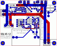
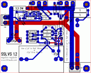
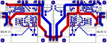
Finally I got some time for the last polishing and addition of the bipolar version - see attached pictures.
@Salas:
Would it be a good idea to short-circuit the two sense-grounds on the PCB of the bipolar version?
EDIT: had an older version of the bipolar one uploaded - fixed.
@Salas:
Would it be a good idea to short-circuit the two sense-grounds on the PCB of the bipolar version?
EDIT: had an older version of the bipolar one uploaded - fixed.
Attachments
Last edited:
No, it would be certainly a bad idea. As it is not that good to short the force ground on the symmetric's pcb too. We need to sense at the error amp, remote discrete consumption points. Not all client builds will have symmetric resistance for sure. Or loops will be created with some incompatible grounding schemes. A good idea would be to make those ground connection points individual, also print Positive Reg, Minus Reg on the double reg too, THKL layout, Salas Design, diyaudio.com has far too many members so to spot us easily.😀
- Status
- Not open for further replies.
- Home
- Amplifiers
- Power Supplies
- The simplistic Salas low voltage shunt regulator


