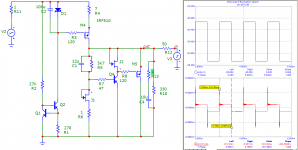
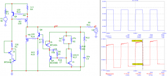
As you can see I was simulating ability to handle changes of output current. Output voltage was set to 24V. Input current was set to 200mA. Current at the output was set to 70 +/- 20 mA.
Peak to peak response of v1.1 was 52 uV and v1.2 was 450 uV. The shape of response is quite different.
It seems to me, that v1.1 is responding a bit better however there maight be other characteristics, that are opposite to this.
Ladislav
Peak to peak response of v1.1 was 52 uV and v1.2 was 450 uV. The shape of response is quite different.
It seems to me, that v1.1 is responding a bit better however there maight be other characteristics, that are opposite to this.
Ladislav
The termination for V1 should be a 470uF plus ESR, R3,R8=220, for 1.2 is either 4.7u+1R or 10u+0.5R, R6=1k(important). Also use higher C1 in 1.2 to get more LF, that one is free to choose.
Hi Salas, I'm going to assemble a V1.2 reg soon and was wondering if there's a substitute for 2N5459? You've said that 2N5457 can be substituted with BF245A, but what about 2N5459? Maybe BF245C ?
Thank you for this project and all your work. 🙂
Thank you for this project and all your work. 🙂
Changed the bipolar version...
I plan on ordering a prototype on the weekend - waiting for additional comments till then...
I think its nice up to where we addressed it from first draft. I don't know more about PCB tricks so no new comment from me. If someone spots something wrong, please comment.
I want to say something about the two 3K3 resistors in the CCS part. Those form a voltage divider so to bias the transistor cascode and feed its LED. Since they are referenced to Vout, there is a scale depending on what voltage region we use the reg, so to always have proper mA through the LED.
For 5Vout use 470R (use Vref 15K instead 27K, use trimmer 3K3 instead 1K, use 2K2 instead 4K3 R6, also when with JFET cascode)
For 10Vout use 1K (use Vref 15K instead 27K, also when with JFET cascode)
For 15Vout use 2K2
For 25Vout use 3K3
For 35Vout use 3K3
For 45Vout use 4K7
Hi Salas, I'm going to assemble a V1.2 reg soon and was wondering if there's a substitute for 2N5459? You've said that 2N5457 can be substituted with BF245A, but what about 2N5459? Maybe BF245C ?
Thank you for this project and all your work. 🙂
You are welcome. What will be the application? Let us know your results.
BF245C and BF244B/C look they might do it. The ones used need to show more than -1V Vgs (OFF) and more than 7mA IDSS.
If min. IDSS required is 7 mA, the BF245A cannot be used then.BF245C and BF244B/C look they might do it. The ones used need to show more than -1V Vgs (OFF) and more than 7mA IDSS.
According to the Philips datasheet I have, VGS min. -0.4 max. -2.2 V (could be OK) but IDSS min. 2 max. 6.5 mA only.
😕 😕 😕
If min. IDSS required is 7 mA, the BF245A cannot be used then.
According to the Philips datasheet I have, VGS min. -0.4 max. -2.2 V (could be OK) but IDSS min. 2 max. 6.5 mA only.
😕 😕 😕
BF245A is a substitute for 2N5457 in the error amp, not in the cascode.
You are welcome. What will be the application? Let us know your results.
BF245C and BF244B/C look they might do it. The ones used need to show more than -1V Vgs (OFF) and more than 7mA IDSS.
I'll be feeding Gigaworks DAC (based on CS4398) it needs two 5v lines and one 3.3v. Right now it is already fed from V1.0 boards (made from Quanghao's schematics using toner-transfer) and the results are quite good, the DAC is sounding way better than with LM317 regs. For 3.3v I just switched shunt element IRFP9240 for BD140, just as you've suggested earlier in the thread. But as always with DIY, I want to upgrade to v1.2 for even better results 🙂 And of course will post the results when i'm done.
Yes, looks like BF245C is indeed can do the trick with Vgs(off) -0.5V to -8V and IDSS of 12mA to 25mA.
Thanks,
Fedor
Don't know off hand if a BD140 can also work in 1.2. They are different regs. Of course you must always lower the shunt's element 120R (now base stopper) to 10-47R. If it will fail, you can still upgrade the 3.3V V1.0 subjectively by using remote sensing if you haven't already.
Don't know off hand if a BD140 can also work in 1.2. They are different regs. Of course you must always lower the shunt's element 120R (now base stopper) to 10-47R. If it will fail, you can still upgrade the 3.3V V1.0 subjectively by using remote sensing if you haven't already.
Yes, I've changed the base stopper to 10R and trimpot to 500R. What about MJE350 instead of BD140, maybe it will do? Or it's the same as BD140?
Thanks,
Fedor
the 340/350 is a high voltage, low current, low fT device. It's no where near an equivalent to the 139/140
Another revision of the PCB:
- slightly changed layout for aesthetics (more symmetric)
- added table for different resistors for different output voltages
For another project (master reference clock) I need a very precise 5V regulator, but I couldn't find the option for 1.2 to add LED reference to the adjustment circuitry.
Does that improve the performance anyhow? What about temperature-drift? The regulator needs to stay very close to 5V all the time...
Are there other regulator desings better suited for that task?
Attachments
for clock you want stable regulator with very low 1/f noise.
If you use LED's, there will be some voltage drifting, see LINK
Precision bandgap devices can be used instead LED, they are more stable (less voltage drifting with temperature change). But they are more noisy as LED's, 1st or 2nd order LPF should be used to filter out noise on error amp input.
If you use LED's, there will be some voltage drifting, see LINK
Precision bandgap devices can be used instead LED, they are more stable (less voltage drifting with temperature change). But they are more noisy as LED's, 1st or 2nd order LPF should be used to filter out noise on error amp input.
As for the rectification and reservoir-capacitors for the bipolar version, what would you suggest?
I thought of something similar to the schematic attached. How much capacitors would you use?
Would you place the transformer, rectifier and capacitors in an additional enclosure?
@Stormsonic: which device would you suggest?! What about AD780?
Are there power-supplies using those devices available anywhere here on diyAudio?
Attachments
If for phono stage and without R-Core Tx, in another box for sure. For other apps it depends on their susceptibility. The PSU loop cabling must be kept short and twisted, most of the times it radiates the better part of a 50 & 100Hz field. 10mF+10mF good quality snap ins and TO-220 modern speed and good recovery diodes would do nicely also. No less than a 50VA Tx for 200mA regs. OK, the real electrical limits are surely lower, especially for lower DCout, but I don't think that anybody would attempt such regs in a skimping mind set.
- Status
- Not open for further replies.
- Home
- Amplifiers
- Power Supplies
- The simplistic Salas low voltage shunt regulator