Headphones are much less reactive, and also by default have a higher series impedance. I don't see why current drive would be a bad thing though. Whether it's worth the effort, I don't know.
- keantoken
- keantoken
Hi Esa,
In the absence of current flow, the magnetic field becomes steady (constant flux), the voice coil exhibiting a purely resistive load.
The magnetic field starts to collapse until there´s no energy stored, the induced voltage falling to zero.
The current generated from the diminishing magnetic field results in an induced a voltage of the same polarity as the driving current, the back EMF now acts as a source of energy, impeding the collapse to maintain an energy conserving equilibrium between input and output power as stated by Lenz's law.
That´s a very regrettable and annoying error indeed, Zem should not be there.For example, in the third equation, either the Blv or Zem should be removed
Right, but deliberately omitted for simplicity.Ze = Re + Le should be Ze = Re + jwLe
During the phase of electric charge build-up from the driving current, the magnetic field is expanding, the back EMF impeding the expansion by preventing a rapid rise of current.'expanding magnetic field'
In the absence of current flow, the magnetic field becomes steady (constant flux), the voice coil exhibiting a purely resistive load.
The magnetic field starts to collapse until there´s no energy stored, the induced voltage falling to zero.
The current generated from the diminishing magnetic field results in an induced a voltage of the same polarity as the driving current, the back EMF now acts as a source of energy, impeding the collapse to maintain an energy conserving equilibrium between input and output power as stated by Lenz's law.
Amplifier output impedance.'external electrical load'
No education actually, just trying to understand things relating to audio, however, the more I think I understand the more I diverge from established opinions.What is your education in electronics?
In a post in another thread, someone posted this:
Originally Posted by Calvin
what current drive promises is:
- a linear frequency response compared to a 6dB-rise with voltage drive
What is usually and too easily forgotten and often not told are the premises and disadvantages of current drive which are:
- cd (current-drive) is not applicable to the entire audio frequency range
- it applies only to the far field range. Under near field conditions, Headphones e.g, linear response is achieved with voltage sources
I'm especially interested by the statement that for headphones "linear response is achieved with voltage sources".
Does that mean that we cannot use current drive for a headphone amp ?
That thread was about electrostatic loudspeakers that are an entirely different world.
Headphones are much less reactive, and also by default have a higher series impedance.
By "much less reactive", you mean that their impedance is mostly resistive and has a very low reactive part, right ?
If that's true, then, indeed, it shouldn't matter whether the amplifier is current or voltage driven since on a purely resistive impedance they are completely equivalent.
Do you have links with data about the typical impedance of a regular (electrodynamic ?) headphone versus frequency ?
I am simply repeating what I have been told about headphones.
No component is purely resistive, they are all reactive somehow. There will be certainly be differences between current and voltage drive with headphones, but I am not in a position to say what is better or to produce specs, or to say whether they are audible.
As far as "typical", about the only certainty is an impedance above 16 ohms and an arbitrary rise in impedance outside the audio band because of coil inductance.
- keantoken
Hi,
some more (boring) reflections...
Acceleration = change of velocity per time interval, velocity = displacement per time interval, the magnitude of velocity is speed, that is change of position per time interval. The product of mass and velocity is momentum (p).
p = mv
F = ma can be written as F = mdv / dt
It now becomes more evident that motion at constant velocity does not result in a force, while motion at constant acceleration results in a (constant) force.
Mechanical work is the amount of energy transferred by a force acting through a distance. Work = force * displacement. Work is not a function of time.
Power is the rate at which energy is converted or work is performed per time interval. Power = force * velocity.
The force formula does not contain displacement since power is not required to create a force, it is required to apply a force over a distance.
Distance refers to how much ground an object has covered, while displacement refers to how far out of place an object is. Movement over a distance does not necessarily result in displacement.
Electromagnetic induction depends entirely on change: any change in the magnetic environment will cause an EMF to be generated that is proportional to the rate of change of the magnetic field flux and to the rate of change of current.
A varying loudspeaker impedance remains a major cause of nonlinearity also with constant current drive.
Generally, distortions rise with increasing power, efficiency and frequency, setting a limit for an achievable level.
In physics, using terms like "eliminate", "remove" and "cancel out" is a bit unfortunate, even if meant symbolically, "transform" is more adequate. Like any electrical properties, distortions cannot be "removed" by any means, they can only be transformed at the expense of higher complex distortions. By definition, any change (except magnitude) to the signal waveform is distortion.
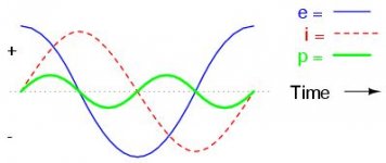
A graphical representation of an idealized inductive circuit.
Since the voltage drop across an inductor is a reaction against the change in current through it, the instantaneous voltage is at a peak when the instantaneous current is at maximum change (the zero line crossing points) and the instantaneous voltage is zero when the instantaneous current is at a peak (zero change).
Since the voltage drop across an inductor is a reaction against the change in current through it, the instantaneous voltage is at a peak when the instantaneous current is at maximum change (the zero line crossing points) and the instantaneous voltage is zero when the instantaneous current is at a peak (zero change).
Attachments
Hi Esa, Hi Guys
Got the book.
I have a quick question. Anyone else welcome to add to it.
Single inductor (Lo-Pass) in series with Bass driver not a problem.
Single capacitor (Hi-Pass) in series with Tweeter not a problem.
But what about using series inductor with a Bass driver that also covers midrange, what will a parallel resistor (shunt) across the voice coil?
It will flatten the Z caused motional EMF below 100 Hertz. I know at least ONE commercial design that does this. But it is on a Bass driver that doesn't go very high and no midrange.
But what if a 2-WAY and the Bass also covers midrange, what effect here? It will also flatten Z due to inductive EMF.
It will as a resistor draw neutral current, and unlike a zobel (negative current). Will it be detrimental to current drive.
Opinons?
Cheers, Joe R.
Hi Guys
I suspect I already know the answer but want fresh perspective on this.
I don't use current drive but I DO use high Z output impedance from tube amps optimised for low open loop distortion, high linearity (under dynamic conditions) etc. Using no global feedback they have relatively high output Z - but nowhere high enough to label current drive.
Cheers, Joe R.
Hi Joe,
I can't answer your question, I probably would make the decision based on subjective impression.
Are you getting a solid bass performance? How is the amp optimized for low distortion?
I can't answer your question, I probably would make the decision based on subjective impression.
Are you getting a solid bass performance? How is the amp optimized for low distortion?
current drive
I have found the extended debate on current drive fascinating.
Such enthusiasm, and at times such erudition!
So now here are a few observations on voltage drive
If it ain't broke don't fix it !
Very good engineering solutions have been found for almost all the problems described for 'voltage drive' .
Voltage drive provides a universal interface to almost all loudspeakers and loudspeaker systems ever made, which deliver performances essentially as intended by the designers.
Well designed voltage drive speakers and systems can deliver very low distortion and stable frequency responses over substantial dynamic range, these generally below audibility thresholds for the working SPLs involved.
Speaker designers routinely address the specific stated problems and have relatively effective (though not perfect) solutions.
Re extra low Qm drivers indicated for current drive I have experienced problems where the extra damping is achieved mechanically in suspension structures where hysteresis may be significant, and this then adds non-linear delay to low frequency transients, upsetting the perception of natural musical rhythms.
I would be interested to know whether current drive addresses this particular matter.
In this industry, compatibility and interchangeability matters immensely and presents a huge barrier to lateral solutions.
The theoretical benefits of current drive are apparent per se but it is the 'new' and more complex execution required which is the barrier, not merely the reported prejudice of the the status quo.
Martin Colloms
Technical Editor HIFICRITIC
If it ain't broke don't fix it !
HiFi has a LONG way to go before it gets anywhere close to its potential i figure. One could argue that that means it is broken.
dave
Martin,
current drive does not offer worthwhile active electrical damping. System Q is the ratio between stored and dissipated energy. The stored energy must be dissipated in some way, mechanically, acoustically or electrically. Generally, at low frequencies I would employ voltage drive as I would expect "problems" there.
current drive does not offer worthwhile active electrical damping. System Q is the ratio between stored and dissipated energy. The stored energy must be dissipated in some way, mechanically, acoustically or electrically. Generally, at low frequencies I would employ voltage drive as I would expect "problems" there.
Dear Martin,
Nice to see you here.
Yes, agreed. There where similar ones years ago on the Sound Practices E-Mail list triggered by posted translations of writings by Ragnar Lien (Driver Designer extraoridinaire and involved at times it seems in all the famous nordic Driver Manufacturers). This was I think even better. There where also other discussions here.
Credit must go to Esa for the extended mathematical workups included in his book, which demonstrate much that has been "suspected" for a long time.
But Martin, this is Diyaudio. If it ain't broke, we break it, fix it, break it again, modify it, break it some more and so on. It is what we do for fun.
This indeed is true. In the last decade plus Driver manufacturers have finally taken notice of the problems of large amounts of HD in their drivers and we now quite commonly see various sorts of flux rings etc. that reduce both inductance and inductance variation and make the eddy-current losses from the voice coil more linear.
Suspensions now often have some non-linearity build in that opposes that of the electrical system for 2nd HD so a modern reflex woofer can have rather lower HD than older designs, which would benefit more from an "air-spring" loading and current drive.
Interestingly I think current drive could have it's greatest benefit in the context of low cost consumer electronics, where the drivers are ultra-cheap and speakers and electronics are still integrated.
One area where conventional engineering has so far failed to produce solutions is thermal compression, less an issue for those listening to light jazz at "pipe and slipper" SPL's, but a significant problem in Pro-Audio and once that is completely cancelled by current drive.
Yes, current, or high impedance drive of speakers is not common, so it cannot be rolled into the industry easily. Yet I can conceive a few options that by now are quite trivial to apply.
One could, for example conceive an Amplifier that can measure the impedance magnitude of the attached speaker with frequency and apply corrections so that the signal is equalised to match the results at voltage drive. One may indeed even add further "auto-EQ" to address the room issues and perhaps sub-ideal frequency response issues not addresses sufficiently by the speaker designer.
Surely this depends on the technical solutions applied to achieve this mechanical damping?
The 1930's era german Eckmiller 12" Coaxial Driver used both a flow-resistance damping (build into the basket) and greasepot damping attached to the Spider to apply damping exclusively in the mechanic domain.
It was incidentally driven from open-loop, Single Ended Pentode Amplifiers which had a very high output impedance. Two of these systems where also used as Monitors for the first high fidelity stereophonic music recordings in 1943 (on the then new BASF Magnetic Tape).
Later versions of the Eckmiller used other innovative technolgical solutions (including driving the coaxial/co-incidental tweeter via inductive coupling from the Woofers voice coil and the use of partially shorted turns to attain woofer damping).
East Germany's O16/17/18 and Schulze TH315 Systems (Eckmiller Derivates produced as main studio monitors) returned to the use of a flow resistance for damping the cone. All these systems had of course dedicated amplifiers that included such solutions as build in Equalisation and what may have been current drive, it is way too long ago that I saw the schematic of one of these Amp's, but the feedback network was unusual.
As a rule, Flow Resistance Damping is quite linear, as is magnetic damping (which is in fact performed in current systems by the low internal impedance of the Amplifier).
So the effect on "pace" from correct solutions to the problem of damping the driver should be at best neutral, however, as any such "direct damping" solution now does not require the Amplifiers feedback system and it's non-linear output impedance (especially for Class AB/Class B systems that have significant hysteresis, or as Douglas Self likes to call it "gm-doubling distortion"), so the usual undesirable issues triggered by using the amplifiers feedback system to damp the driver using it's back EMF are avoided.
While this is true, things like current drive etc. can be easily implemented in modern active speakers, which are becoming more prevalent. So it remains puzzling that no such attempts are undertaken.
It could especially help in the case of Subwoofers, as proven nearly five decades ago, by late Louis W Erath with the "ES" (Electronic Suspension) Woofer system (which devolves primarily to current/high impedance drive at higher frequencies and voltage drive& 2nd order equalisation al lower frequencies).
In fact, I have observed that current drive seems to come back in around generation intervals. LWE made his experiments in the late 50's and early 60's. In the mid 80's I came across "current drive" (and other interesting systems such as negative resistance and motional feedback) in the common literature and implemented various of these solutions in an experimental active speaker. And now in the 2K's we are again talking about current drive.
In the end, it seems that the overall benefits are insufficient to sway the purely profit oriented Audio Industry as a whole, while nevertheless individual examples of "current drive" systems show the potential of this technique.
In fact, with your undeniable position of authority in the whole area of High End Speakers, why not investigate some more and add some chapters on CD to the next edition of your book?
I previously suggested a possible experimental active system to use current drive (Seas Coaxial plus Seas Woofer as Dipole) that may make a good and effective practical experiment in several "lateral" technologies and make make good material for publication.
Ciao T
Nice to see you here.
I have found the extended debate on current drive fascinating.
Yes, agreed. There where similar ones years ago on the Sound Practices E-Mail list triggered by posted translations of writings by Ragnar Lien (Driver Designer extraoridinaire and involved at times it seems in all the famous nordic Driver Manufacturers). This was I think even better. There where also other discussions here.
Credit must go to Esa for the extended mathematical workups included in his book, which demonstrate much that has been "suspected" for a long time.
So now here are a few observations on voltage drive
If it ain't broke don't fix it !
But Martin, this is Diyaudio. If it ain't broke, we break it, fix it, break it again, modify it, break it some more and so on. It is what we do for fun.
Very good engineering solutions have been found for almost all the problems described for 'voltage drive'.
This indeed is true. In the last decade plus Driver manufacturers have finally taken notice of the problems of large amounts of HD in their drivers and we now quite commonly see various sorts of flux rings etc. that reduce both inductance and inductance variation and make the eddy-current losses from the voice coil more linear.
Suspensions now often have some non-linearity build in that opposes that of the electrical system for 2nd HD so a modern reflex woofer can have rather lower HD than older designs, which would benefit more from an "air-spring" loading and current drive.
Interestingly I think current drive could have it's greatest benefit in the context of low cost consumer electronics, where the drivers are ultra-cheap and speakers and electronics are still integrated.
One area where conventional engineering has so far failed to produce solutions is thermal compression, less an issue for those listening to light jazz at "pipe and slipper" SPL's, but a significant problem in Pro-Audio and once that is completely cancelled by current drive.
Voltage drive provides a universal interface to almost all loudspeakers and loudspeaker systems ever made, which deliver performances essentially as intended by the designers.
Yes, current, or high impedance drive of speakers is not common, so it cannot be rolled into the industry easily. Yet I can conceive a few options that by now are quite trivial to apply.
One could, for example conceive an Amplifier that can measure the impedance magnitude of the attached speaker with frequency and apply corrections so that the signal is equalised to match the results at voltage drive. One may indeed even add further "auto-EQ" to address the room issues and perhaps sub-ideal frequency response issues not addresses sufficiently by the speaker designer.
Re extra low Qm drivers indicated for current drive I have experienced problems where the extra damping is achieved mechanically in suspension structures where hysteresis may be significant, and this then adds non-linear delay to low frequency transients, upsetting the perception of natural musical rhythms.
Surely this depends on the technical solutions applied to achieve this mechanical damping?
The 1930's era german Eckmiller 12" Coaxial Driver used both a flow-resistance damping (build into the basket) and greasepot damping attached to the Spider to apply damping exclusively in the mechanic domain.
It was incidentally driven from open-loop, Single Ended Pentode Amplifiers which had a very high output impedance. Two of these systems where also used as Monitors for the first high fidelity stereophonic music recordings in 1943 (on the then new BASF Magnetic Tape).
Later versions of the Eckmiller used other innovative technolgical solutions (including driving the coaxial/co-incidental tweeter via inductive coupling from the Woofers voice coil and the use of partially shorted turns to attain woofer damping).
East Germany's O16/17/18 and Schulze TH315 Systems (Eckmiller Derivates produced as main studio monitors) returned to the use of a flow resistance for damping the cone. All these systems had of course dedicated amplifiers that included such solutions as build in Equalisation and what may have been current drive, it is way too long ago that I saw the schematic of one of these Amp's, but the feedback network was unusual.
As a rule, Flow Resistance Damping is quite linear, as is magnetic damping (which is in fact performed in current systems by the low internal impedance of the Amplifier).
So the effect on "pace" from correct solutions to the problem of damping the driver should be at best neutral, however, as any such "direct damping" solution now does not require the Amplifiers feedback system and it's non-linear output impedance (especially for Class AB/Class B systems that have significant hysteresis, or as Douglas Self likes to call it "gm-doubling distortion"), so the usual undesirable issues triggered by using the amplifiers feedback system to damp the driver using it's back EMF are avoided.
In this industry, compatibility and interchangeability matters immensely and presents a huge barrier to lateral solutions.
While this is true, things like current drive etc. can be easily implemented in modern active speakers, which are becoming more prevalent. So it remains puzzling that no such attempts are undertaken.
It could especially help in the case of Subwoofers, as proven nearly five decades ago, by late Louis W Erath with the "ES" (Electronic Suspension) Woofer system (which devolves primarily to current/high impedance drive at higher frequencies and voltage drive& 2nd order equalisation al lower frequencies).
In fact, I have observed that current drive seems to come back in around generation intervals. LWE made his experiments in the late 50's and early 60's. In the mid 80's I came across "current drive" (and other interesting systems such as negative resistance and motional feedback) in the common literature and implemented various of these solutions in an experimental active speaker. And now in the 2K's we are again talking about current drive.
In the end, it seems that the overall benefits are insufficient to sway the purely profit oriented Audio Industry as a whole, while nevertheless individual examples of "current drive" systems show the potential of this technique.
In fact, with your undeniable position of authority in the whole area of High End Speakers, why not investigate some more and add some chapters on CD to the next edition of your book?
I previously suggested a possible experimental active system to use current drive (Seas Coaxial plus Seas Woofer as Dipole) that may make a good and effective practical experiment in several "lateral" technologies and make make good material for publication.
Ciao T
Have to disagree here. Current-drive makes the various electrical impedances disappear from disturbing the driving force generation. Impedance variations then show up only as corresponding voltage fluctuations, doing no harm anywhere.WuYit said:A varying loudspeaker impedance remains a major cause of nonlinearity also with constant current drive.
What? Distortions have been removed and eliminated by various means down the ages. That's the main point of the exercise.WuYit said:In physics, using terms like "eliminate", "remove" and "cancel out" is a bit unfortunate, even if meant symbolically, "transform" is more adequate. Like any electrical properties, distortions cannot be "removed" by any means, they can only be transformed at the expense of higher complex distortions.
Depends on the definition. In engineering terms, distortion usually means extraneous frequencies at the output not present at the input. Mere phase shifts or frequency response variations, that also shape the waveform, are generally not regarded as distortion, unless we are specifically considering these waveform, i.e. linear, distortions.WuYit said:By definition, any change (except magnitude) to the signal waveform is distortion.
Hi, JoeJoe Rasmussen said:But what about using series inductor with a Bass driver that also covers midrange, what will a parallel resistor (shunt) across the voice coil?
It will flatten the Z caused motional EMF below 100 Hertz. I know at least ONE commercial design that does this. But it is on a Bass driver that doesn't go very high and no midrange.
But what if a 2-WAY and the Bass also covers midrange, what effect here? It will also flatten Z due to inductive EMF.
It will as a resistor draw neutral current, and unlike a zobel (negative current). Will it be detrimental to current drive.
If I correctly interpret your question, you mean what a shunt resistor does to the driving mode. It always decreases the impedance seen by the driver and hence shifts the operation closer to voltage drive. Though it will flatten Z, not very suitable for current-drive.
Can you give an example of an affordable DIY driver that is so free from any distortions for the working SPLs?Martin Colloms said:Well designed voltage drive speakers and systems can deliver very low distortion and stable frequency responses over substantial dynamic range, these generally below audibility thresholds for the working SPLs involved.
By applying enough copper rings, the inductive EMF and effects related to it can definitely be reduced, but I don't see much practical means to address the motional EMF at mid-frequencies, except by decreasing sensitivity, which is out of question at least in pro gear.
I have also faced certain nonlinearity problems with some low-Q suspensions, but have also noticed it to be very much dependent on the rubber grade. In bygone years, it was usual that the resonant frequency at 1 mA current was even 40% higher than at 100 mA; but with newer drivers and materials, the difference can be as low as a few percents. According to my experience, those nonlinear rubbers were also very UV-sensitive and hardened when exposed to daylight, but fortunately this is not so common any more.Martin Colloms said:Re extra low Qm drivers indicated for current drive I have experienced problems where the extra damping is achieved mechanically in suspension structures where hysteresis may be significant,
Hi Esa,
firstly, I would like to express my sincere appreciation for your work.
Many types of distortion are defined and explored, like frequency and phase distortion, but due to difficulties to measure, the more manageable harmonic distortion is blamed for almost all inconveniences. In my opinion, harmonic distortion is benign and should not be "removed".
firstly, I would like to express my sincere appreciation for your work.
Please don`t misunderstand me entirely. I`ve been trying to say all along, in agreement with a very few people here, that distortions are significantly reduced with current drive. However, an ohmic loudspeaker impedance gives lower distortion under any circumstances, constituting a much more gentle load to the amplifier even if it`s low.Have to disagree here. Current-drive makes the various electrical impedances disappear from disturbing the driving force generation. Impedance variations then show up only as corresponding voltage fluctuations, doing no harm anywhere.
It´s exactly what I`m denying. Once present at the output, distortions will stay in some form. Distortions cannot be "removed" in a surgical manner and the commonly used feedback is anything but a precision instrument. Natural sounds, particularly music signals have an immense complexity. Any attempt to correction (l would agree on calling it energy redistribution or transformation) will more or less harm the signal. Dynamically, every change in the music content gives rise to an infinite number of created harmonics, making any kind of trustworthy analysis impossible.Distortions have been removed and eliminated by various means down the ages.
What I meant was that the change in the signal made by the distortion reduction and error correction techniques represents distortion. A lower measured distortion can be explained by limited measurement capabilities.Depends on the definition. In engineering terms, distortion usually means extraneous frequencies at the output not present at the input. Mere phase shifts or frequency response variations, that also shape the waveform, are generally not regarded as distortion, unless we are specifically considering these waveform, i.e. linear, distortions.
Many types of distortion are defined and explored, like frequency and phase distortion, but due to difficulties to measure, the more manageable harmonic distortion is blamed for almost all inconveniences. In my opinion, harmonic distortion is benign and should not be "removed".
Esa,
Linearity greatly improves as voice coil inductance approaches zero.
Independently of drive mode, loudspeaker linearity will be improved, at the necessary cost of decreased efficiency, through reduced permeability, thereby reduced voice coil inductance, reduced inductance modulation and reduced magnetic flux modulation.By applying enough copper rings, the inductive EMF and effects related to it can definitely be reduced, but I don't see much practical means to address the motional EMF at mid-frequencies, except by decreasing sensitivity, which is out of question at least in pro gear.
Linearity greatly improves as voice coil inductance approaches zero.
Wouldn't making the coil smaller increase efficiency by allowing to use lower voltage rails for the amp? Or at least considering this be equal?
- keantoken
- keantoken
ThorstenL ,
Output stages should be class A biased for normal listening levels.
The bipolar transistor output stage "optimal" bias theory in conjunction with gm-doubling distortion comprises some of the many perplexing findings made by D. Self. However, it applies the class A overlap region so he prescribes a low operating point. Gm-doubling distortion is subjectively mild compared to the highly objectionable switching and crossover distortion (although it´s part of the crossover distortion). Rather the scanty Gm near cutoff that causes substantial distortion, particularly low level input signals will be severely distorted or not amplified at all. Also, the load resistance limits the transconductance and Gm will vary wildly with current and temperature. Transition characteristics are device specific, why would a certain voltage drop on emitter resistor generally signify an "optimal" quiescent current?So the effect on "pace" from correct solutions to the problem of damping the driver should be at best neutral, however, as any such "direct damping" solution now does not require the Amplifiers feedback system and it's non-linear output impedance (especially for Class AB/Class B systems that have significant hysteresis, or as Douglas Self likes to call it "gm-doubling distortion"), so the usual undesirable issues triggered by using the amplifiers feedback system to damp the driver using it's back EMF are avoided.
Output stages should be class A biased for normal listening levels.
Hi,
I do not neccesarily follow D. Self's dictums, as he and I have radically different goals (he a "blameless" Amplifer, me a good sounding one).
I raise this, because especially in low feedback PP Amp's the modulation of the amplifiers output impedance around the zero crossing can be quite material. This is a dynamic phenomena that will interact with the drivers mechanical behaviour in ways not easily predicted by measurements with a resistive load.
Ciao T
The bipolar transistor output stage "optimal" bias theory in conjunction with gm-doubling distortion comprises some of the many perplexing findings made by D. Self.
...
Output stages should be class A biased for normal listening levels.
I do not neccesarily follow D. Self's dictums, as he and I have radically different goals (he a "blameless" Amplifer, me a good sounding one).
I raise this, because especially in low feedback PP Amp's the modulation of the amplifiers output impedance around the zero crossing can be quite material. This is a dynamic phenomena that will interact with the drivers mechanical behaviour in ways not easily predicted by measurements with a resistive load.
Ciao T
- Status
- Not open for further replies.
- Home
- Vendor's Bazaar
- The Secret of Tube Amplifiers Revealed - and much more!