As for the paradigms, the operation of the speaker diver is based on the simple yet neglected law: F=Bli, that is, the driving force, that determines cone acceleration according to the Newtonian law F=ma and hence the sound pressure generated, obeys only and solely current; the voltage between the ends of the wire or the power consumed by the driver don't appear anywhere in these equations. Basically, it is as simple as that. (B is here the flux density that exists when the current is zero. The current causes always its own magnetic field, that may react with adjacent iron, but the effect is not related to this equation.)
To depart from the clear direction of the above current law would require very strong justifications, but electrical damping, that can only be used to shape the frequency response near the fundamental resonance and has no effect anywhere else, is not any justification to perform against the current-law at the middle and treble frequencies.
The practice that is called power drive is sort of an electrical halfway between voltage and current drive; thus very understandably the power paradigm finds its advocates, but as I have remarked, there is no real reason to stay at any halfway solutions when we can as well pursue the whole solution.
The damping article mentioned has merit in the sense that it shows that regarding the damping factor, 'the higher the better' is not true. However, we can never get real answers to the actual question of best output impedance by focusing all attention merely on the bass region damping. The step response decay times are only reflections of the bass frequency response, as explicitly determined by the Fourier transform relationship, and tell nothing about the sonic character of the drive methods in the main frequency areas.
It is important to realize that damping and the Q value of the driver-enclosure combination have effect only near the resonant frequency. Instead, at all other frequencies, from about 200 Hz up for woofers, any driver damping doesn't have any effect at all. This can also be demonstrated by basic modeling and can also be seen in the response curves presented in the article mentioned.
The motional EMF of the driver can actually be called a back-EMF only in the resonance region, where this EMF voltage acts about in phase with the applied signal and therefore reduces the flow of current on voltage drive, thus effecting the damping. Instead, when frequency rises from the resonance region, the EMF voltage soon turns perpendicular to the resistive voltage and current and at the same time decreases in magnitude, going below the resistive component typically at some 150 Hz or so. Thus, in the whole mid-frequency region, the motional EMF no more damps or controls anything but acts merely as an uncontrolled interference source between driver voltage and current, doing nothing useful.
This is what the issue is about, along with the equally deleterious effects of the vague voice coil inductance.
Hi ETM,
Well put, and I'm in complete agreement with you on this. You explained a speaker at resonance well, from a different direction than is normally taken. As a result, I think you drove home some points that are often overlooked by many. When testing loudspeakers, I look for 0 ° phase shift to confirm I'm at the resonant point. It's also a great way to tell if there are non-linearities in the speaker as that tends to open up the pattern. You can find some really interesting defects with a speaker that way too.
I'm still not sure that current drive is the answer to everything. It is a better way to go in some situations, that is not in dispute. Still, you have to avoid trying to use one tool for every situation.
"If what you have is a hammer, every problem appears to be a nail".
Hi atmasphere,
Very good links, thank you.
-Chris
Inquiry
Hi ETM,
I find your thesis quite interesting, but there is still one thing that bothers me. Even with current drive we should expect a certain level of non-linearity to occur, If for no good reason, then due to the fact that nothing is perfectly linear. In reality current will not translate linearly into force through the relation F=BIL, also damping and stiffness coefficients are expected to be nonlinear. So my question is, is there an intuitive explanation why should the resulting non-linearity from current drive be any improvement to that resulting from voltage drive, taking into consideration that eq. (3.14) in the book relating displacement to voltage is also a linear transfer function (quite similar to eq. 3.4 relating displacement to current)
In other words, if the speaker mechanical model (motional impedance) is assumed to be linear, then both the current and voltage drive scenarios will yield linear responses, if the motional impedance is considered non-linear then both scenarios will give non-linear responses, so why should the current case fundamentally be more superior?
Hi Yousr
I assume you have been reading the sample pages provided, that are mostly of chapter 3.
The nonlinearity and interference effects that current-drive eliminates are disclosed in chapter 4 (outlined also on the website and listed here in post #193) and occur mostly at the middle and treble frequencies. In the bass region, where the damping and stiffness coefficients only have effect, the driving mode is not so important. The transfer functions you mentioned model the behavior of a perfect driver at low frequencies and of course must have linearity as the basic assumption (as with any transfer function).
Nonlinearity of the motional impedance itself does not cause any response nonlinearity on current-drive. If the mechanical parameters (stiffness, damping constant, mass) or Bl are nonlinear, distortion ensues irrespective of the drive mode, but current-drive keeps the response pure from any corruption occurring in the motional impedance as well as in the inductive impedance. Both of these appear in series with the DC resistance and disturb the critical voltage/current conversion throughout the middle and treble regions.
Hoping this clarifies
I assume you have been reading the sample pages provided, that are mostly of chapter 3.
The nonlinearity and interference effects that current-drive eliminates are disclosed in chapter 4 (outlined also on the website and listed here in post #193) and occur mostly at the middle and treble frequencies. In the bass region, where the damping and stiffness coefficients only have effect, the driving mode is not so important. The transfer functions you mentioned model the behavior of a perfect driver at low frequencies and of course must have linearity as the basic assumption (as with any transfer function).
if the motional impedance is considered non-linear then both scenarios will give non-linear responses, so why should the current case fundamentally be more superior?
Nonlinearity of the motional impedance itself does not cause any response nonlinearity on current-drive. If the mechanical parameters (stiffness, damping constant, mass) or Bl are nonlinear, distortion ensues irrespective of the drive mode, but current-drive keeps the response pure from any corruption occurring in the motional impedance as well as in the inductive impedance. Both of these appear in series with the DC resistance and disturb the critical voltage/current conversion throughout the middle and treble regions.
Hoping this clarifies
interesting!The nonlinearity and interference effects that current-drive eliminates <...> occur mostly at the middle and treble frequencies. In the bass region, where the damping and stiffness coefficients only have effect, the driving mode is not so important.
Then one may think of using current drive only at mid and higher frequencies while reverting to voltage drive to achieve required speaker damping in the bass region?

This would be easily achievable e.g. by wrapping a frequency-dependent (parallel) voltage NFB loop around a current-source type amplifier and perhaps could allow the use of (some of the) existing speakers systems without modification, removing one of the biggest critics which have been made to the current drive idea.
I guess that at least single-driver and multi-amped speakers should be useable this way. Not sure about (passive) multi-way ones, but I am afraid that the driving impedance variations may interact with the passive cross-over and badly alter the overall frequency response... 😕
Last edited:
Hi,
This is pretty much what I did in the 1980's.
I build (for personal use) a 3-Way tower, all active. It started as a basic "active crossover" speaker, but in the final configuration I used a lot of techniques that where considered completely cutting edge at the time.
The Midrange was a 5" Paper Cone wideband driver, this was running from 250Hz to 5KHz and was driven in "current mode".
Treble was a 1" Plastic Dome Tweeter, also current drive.
Bass was with two 8" Drivers, voltage drive and microphone based motional feedback.
Crossovers where 4th order LR in the end, earlier I had used 3rd order butterworth.
This worked rather well, but in the end I preferred various other speaker/amplifier combos over this, not the least the Schulze TH315 12" Coax with (modified) matching Amp.
Ciao T
Then one may think of using current drive only at mid and higher frequencies while reverting to voltage drive to achieve required speaker damping in the bass region?
This is pretty much what I did in the 1980's.
I build (for personal use) a 3-Way tower, all active. It started as a basic "active crossover" speaker, but in the final configuration I used a lot of techniques that where considered completely cutting edge at the time.
The Midrange was a 5" Paper Cone wideband driver, this was running from 250Hz to 5KHz and was driven in "current mode".
Treble was a 1" Plastic Dome Tweeter, also current drive.
Bass was with two 8" Drivers, voltage drive and microphone based motional feedback.
Crossovers where 4th order LR in the end, earlier I had used 3rd order butterworth.
This worked rather well, but in the end I preferred various other speaker/amplifier combos over this, not the least the Schulze TH315 12" Coax with (modified) matching Amp.
Ciao T
If you put a correctly designed copper ring or cap into the voicecoil gap it does not matter any more if the amp has current or voltage drive. (...)
Beg to disagree. The problem of inductance variation solved, but nothing else.
Force with current drive is proportional to Bxl, whereas with voltage drive, it is proportional to (Bxl)^2.
The Bxl curve of any loudspeaker is non-linear with excursion (even if some designs are more linear than others), and current drive will react more gracefully.
why higher midrange distortion?
Just read the review in the July 10 issue of Voice Coil.
The reviewer measured distortion on a W15CY in a sealed enclosure. Distortion at or below resonance was higher for current drive. This is probably a case of harmonics amplfication (the harmonics of a sub-resonance signal are likely to be near resonance, which in the case of current drive is less damped). Basically no surprise there, except I would not have expected the curve to increase smoothly towards LF, but rather exhibit modes at 1/2, 1/3, 1/4 of fs.
The real surprise was midrange distortion which was much more equal, but still showed consistently higher distortion for current drive.
This is in complete contradiction to theory. Any ideas?
Reconfiguring an amp for current drive is not necessarily simple, and done improperly may impair the performance of the amp. Also, if the current driven speaker uses passive components for EQ, these might come under suspicion.
Also, some magnets are constructed specifically to reduce this kind of distortion, for instance the Xbl^2 motor. Something like this would probably perform worse with current drive because the distortions it cancels out are no longer present.
However it is hard to tell anything if we don't have access to the original article.
- keantoken
Last edited:
This is a very interesting thread, but I didn't have time to read it all.
In a few words, what is the main advantage of current driving over voltage driving ? Is it a reduction in distortions ? What kind of distortion and how much can is the reduction ?
In a few words, what is the main advantage of current driving over voltage driving ? Is it a reduction in distortions ? What kind of distortion and how much can is the reduction ?
You can read the first 60 pages of the book in the Amazon preview, and you can also look through The dedicated site here:
Current-Driving of Loudspeakers
Post 205 sums much of it up I think, but elsewhere in the thread are better posts.
- keantoken
Current-Driving of Loudspeakers
Post 205 sums much of it up I think, but elsewhere in the thread are better posts.
- keantoken
is that article available somewhere on the net?Just read the review in the July 10 issue of Voice Coil.
The same review was published in the July issues of Audioxpress and Voice Coil. I have sent them my comments on the review already in July and have understood they are going to run my letter in Audioxpress but not in Voice Coil. Perhaps in the November issue.
is that article available somewhere on the net?
VC is by subscription only. However, it is quite easy to get one as a "professional"
Hi,
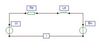
the conversion of electrical to acoustical energy takes place at the cost of high distortions and large losses. Unfortunately, from a practical point of view, distortions and losses are inversely related. The main energy conversions carried out in loudspeakers are voltage-to-current, current-to-voltage, electrical-to-kinetic, kinetic-to-electrical, and kinetic-to-acoustical.
The familiar law of winding force
F = Bli
where
Bl = motor strength
i = input current
The back EMF induces an opposing voltage proportional to voice coil velocity by converting mechanical energy of motion to electrical energy. Due to the presence of an external electrical load a harmful current will enter the amplifier.
e = - Blv
where
e = induced voltage
v = velocity of motion
When the input signal is a voltage, the course of events gets considerably more turbulent as the voltage-to-current conversion occurs according to
i = Vi - Blv / Ze + Zem
where
i = output current
Vi = input voltage
Ze = electrical impedance, consisting of voice coil DC resistance and voice coil inductance
Zem = electrical motional impedance created by the back EMF; during an expanding magnetic field the back EMF acts as a load, the voltage is 180° out of phase counteracting the current flow, thereby increasing the electrical impedance, basically Zem = e / i
Ze = Re + Le
v = Bli / Zmt
where
Zmt = total mechanical impedance (the ratio of force and velocity)
Substituting Ze and v provides a more detailed definition
i = Vi / (Re + Le) + (Bl)² / Zmt
Now the electrical motional impedance appears as
Zem = (BL)² / Zmt
And the motor force is given by
F = (Bl)Vi / (Re + Le) + (Bl)² / Zmt
The function of the permanent magnet moving-coil motor is governed by instantaneous, constantly varying, strongly interactive parameters, constituting a well-founded basis for concern when a linear mechanical motion is desirable. The most deleterious product of the nonlinear interaction between the static and the AC magnetic field is an inductance that brings about a rise in impedance, restricting the driving current, altering the frequency response, causing harmonic, intermodulation and phase distortion.
The intrinsic fluctuations in load impedance undermine the accuracy of the crucial voltage-to-current conversion and exacerbates the vicious circle of nonlinear modulations.
In order to significantly reduce distortions both in the loudspeaker and in the amplifier, the signal needs to be a current, supplied from a transconductance amplifier with high port impedances. The aim should be high isolation between amplifier and loudspeaker, between amplifying stages and between their input and output terminals.
Not very oddly, for good proportionality between the output voltage and the input current, the EMF voltage source needs to approach the properties of an ideal voltage source, and again, it needs to be supplied from a (nearly ideal) current source.
Attachments
The review and my letter, that appeared in the November issue of Audioxpress, are now available here. (The file is somewhat heavy but working.)
WuYit, there is truth but also some error in your presentation. For example, in the third equation, either the Blv or Zem should be removed; and the relation Ze = Re + Le should be Ze = Re + jwLe, where 'w' is the angular frequency. Also, the expressions 'expanding magnetic field' and 'external electrical load' are left quite unclear to me. What is your education in electronics?
WuYit, there is truth but also some error in your presentation. For example, in the third equation, either the Blv or Zem should be removed; and the relation Ze = Re + Le should be Ze = Re + jwLe, where 'w' is the angular frequency. Also, the expressions 'expanding magnetic field' and 'external electrical load' are left quite unclear to me. What is your education in electronics?
In a post in another thread, someone posted this:
I'm especially interested by the statement that for headphones "linear response is achieved with voltage sources".
Does that mean that we cannot use current drive for a headphone amp ?
what current drive promises is:
- a linear frequency response compared to a 6dB-rise with voltage drive
What is usually and too easily forgotten and often not told are the premises and disadvantages of current drive which are:
- cd (current-drive) is not applicable to the entire audio frequency range
- it applies only to the far field range. Under near field conditions, Headphones e.g, linear response is achieved with voltage sources
I'm especially interested by the statement that for headphones "linear response is achieved with voltage sources".
Does that mean that we cannot use current drive for a headphone amp ?
- Status
- Not open for further replies.
- Home
- Vendor's Bazaar
- The Secret of Tube Amplifiers Revealed - and much more!